Image stabilization device, image stabilization method, and program

a technology of image stabilization and image, which is applied in the direction of 2d-image generation, image analysis, instruments, etc., can solve the problems of increased shaking of the display image seen from increased so as to reduce the fatigue of the user, reduce the shaking of the display image, and reduce the effect of the user's point of view

Inactive Publication Date: 2011-12-08
SONY CORP
View PDF5 Cites 8 Cited by
  • Summary
  • Abstract
  • Description
  • Claims
  • Application Information

AI Technical Summary

Benefits of technology

[0008]However, a delay occurs between the timing of occurrence of shaking of a portable appliance and the timing of motion compensation of a display image due to computational processing or the like. Thus, in the case the shaking of the portable appliance is weak, the phase of the shaking of the portable appliance and the phase of shaking given to the display image will be approximately opposite, but in the case the shaking of the portable appliance is intense, the phases of the shaking will not be opposite. In some cases, the phases of the shaking are intensified by each other. As a result, shaking of the display image seen from the user's point of view is increased and will be even more tiring to the optic nerve of the user.
[0009]For example, when using the portable appliance on a bouncing vehicle, a fine shaking is likely to occur on the portable appliance. Accordingly, if the technology of the patent document described above is applied, discrepancy between phases occurs frequently between the shaking of the portable appliance and the shaking given to the display image to cancel the above-mentioned shaking, and thus the shaking of the display image relative to the user's point of view is even more increased. Furthermore, eyes of a human have a function of following the motion of a viewing target. Thus, even if the display image is not completely still relative to the user's point of view, the display image can be correctly viewed.
[0010]In light of the foregoing, it is desirable to provide an image stabilization device, an image stabilization method, and a program which are novel and improved, and which are capable of reducing shaking of a display image relative to a user's point of view on a per-layer basis in the case shaking of a portable appliance occurs, thereby further reducing the fatigue of the user.
[0011]According to the embodiments described above, it is possible to reduce shaking of a display image relative to a user's point of view on a per-layer basis in the case shaking of a portable appliance occurs, thereby further reducing the fatigue of the user. In some embodiments, the image stabilization may comprise detecting motion of an apparatus configured to display image data, and processing the image data to correct for the detected motion. In some embodiments, the processing may comprise applying motion correction to layers of the image data, by moving the layers in a direction opposing the detected motion. In some embodiments, different degrees of motion correction may be applied to different layers and / or to different types of layers.

Problems solved by technology

However, a delay occurs between the timing of occurrence of shaking of a portable appliance and the timing of motion compensation of a display image due to computational processing or the like.
As a result, shaking of the display image seen from the user's point of view is increased and will be even more tiring to the optic nerve of the user.
For example, when using the portable appliance on a bouncing vehicle, a fine shaking is likely to occur on the portable appliance.
Accordingly, if the technology of the patent document described above is applied, discrepancy between phases occurs frequently between the shaking of the portable appliance and the shaking given to the display image to cancel the above-mentioned shaking, and thus the shaking of the display image relative to the user's point of view is even more increased.

Method used


Image

  • Image stabilization device, image stabilization method, and program
  • Image stabilization device, image stabilization method, and program
  • Image stabilization device, image stabilization method, and program

Examples


first embodiment

1: First Embodiment

[0070]A first embodiment will be described. The present embodiment relates to a method of reducing shaking of a display image occurring in relation to a user's point of view in a situation where shaking is caused on a portable appliance 10. Note that this method is not for “stilling” a display image in relation to a user's point of view, but for “reducing” the shaking of the display image to reduce the fatigue of the user.

1-1: Functional Configuration of Portable Appliance 10

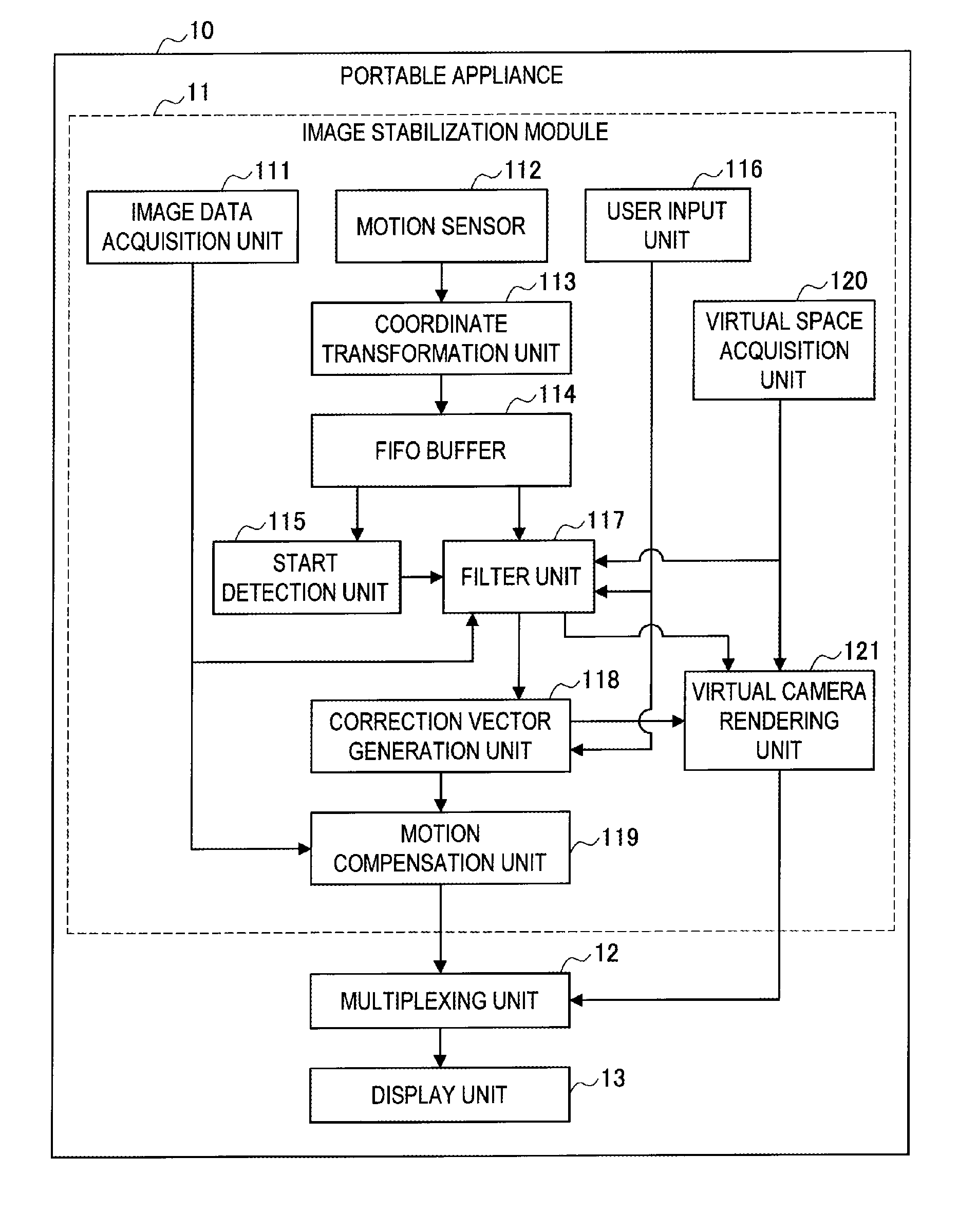
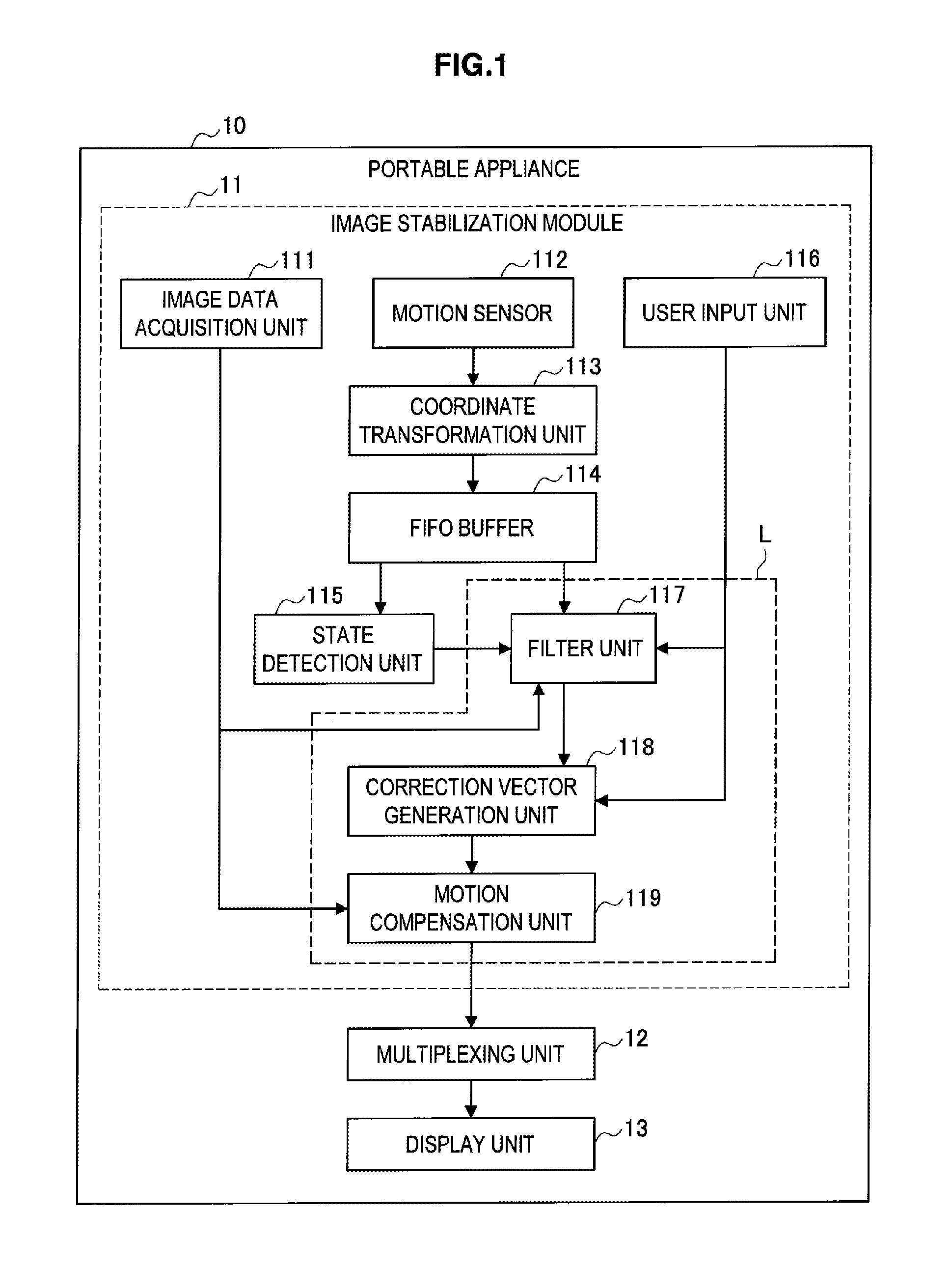
[0071]First, a functional configuration of the portable appliance 10 according to the present embodiment will be described with reference to FIG. 1. FIG. 1 is an explanatory diagram showing a functional configuration of the portable appliance 10 according to the present embodiment.

[0072]As shown in FIG. 1, the portable appliance 10 mainly includes an image stabilization module 11, a multiplexing unit 12, and a display unit 13. The image stabilization module 11 is means for reducing shaking of ...

second embodiment

2: Second Embodiment

[0153]Next, a second embodiment will be described. The present embodiment relates to a method of adjusting applied cancellation strength on an operation object according to an operation status of a user.

[0154][2-1: Functional Configuration of Portable Appliance 10]

[0155]First, a functional configuration of the portable appliance 10 according to the present embodiment will be described with reference to FIG. 18. FIG. 18 is an explanatory diagram showing a functional configuration of the portable appliance 10 according to the present embodiment. Additionally, structural elements that have substantially the same function as those of the portable appliance 10 according to the first embodiment above will be denoted with the same reference numerals, and detailed explanation of these structural elements will be omitted.

[0156]As shown in FIG. 18, the portable appliance 10 mainly includes an image stabilization module 11, a multiplexing unit 12, and a display unit 13. The...

third embodiment

3: Third Embodiment

[0174]Next, a third embodiment will be described. The present embodiment relates to a method of determining filter strength according to the depth of the perspective (depth) of a three-dimensional virtual space.

[0175][3-1: Functional Configuration of Portable Appliance 10]

[0176]First, a functional configuration of a portable appliance 10 according to the present embodiment will be described with reference to FIG. 22. FIG. 22 is an explanatory diagram showing a functional configuration of a portable appliance 10 according to the present embodiment. Additionally, structural elements that have substantially the same function as those of the portable appliance 10 according to the first embodiment above will be denoted with the same reference numerals, and detailed explanation of these structural elements will be omitted.

[0177]As shown in FIG. 22, the portable appliance 10 mainly includes an image stabilization module 11, a multiplexing unit 12, and a display unit 13. ...


PUM


Abstract

Techniques for image stabilization may include detecting motion of an apparatus configured to display image data, the image data comprising one or more frames, a first frame of the one or more frames comprising a plurality of layers. The plurality of layers may be processed to correct for the detected motion. The processing may comprise applying a different degree of motion correction to a first layer of the plurality of layers than to a second layer of the plurality of layers. Such techniques may be performed via an apparatus comprising a display control unit configured to cause the image data to be displayed, and a motion correction unit configured to perform the processing.

Description

BACKGROUND[0001]1. Field[0002]Some embodiments described in the present application relate to an image stabilization device, an image stabilization method, and a program.[0003]2. Description of the Related Art[0004]In recent years, small electronic appliances (hereinafter, portable appliances) such as a mobile phone, a portable game machine, a portable information terminal, a notebook computer (hereinafter, notebook PC), a portable music player, a digital video camera, a digital still camera (hereinafter, image pickup device), and the like have come to be widely used. These portable appliances are used in various places. For example, users are seen to be using the portable appliances on a vehicle while moving, on a street corner, in a waiting room in an office building, in the living room at home, and the like.[0005]As such, use scenes are becoming more various as the portable appliances are made smaller and their portability is increased. However, although the effect of increase in...

Claims


Application Information

Patent Timeline
Patent Type & Authority Applications(United States)
IPC IPC(8): G06K9/40
CPCG06T7/20G06T11/00
Inventor SAKAGUCHI, TATSUMIOGAWA, NOBUHIROWATANABE, SHINJI
Owner SONY CORP
Why Eureka
Try Eureka