
Special application light for light strings

Inactive Publication Date: 2007-04-12
BEST POINT GROUP
View PDF24 Cites 3 Cited by
  • Summary
  • Abstract
  • Description
  • Claims
  • Application Information

AI Technical Summary

Benefits of technology

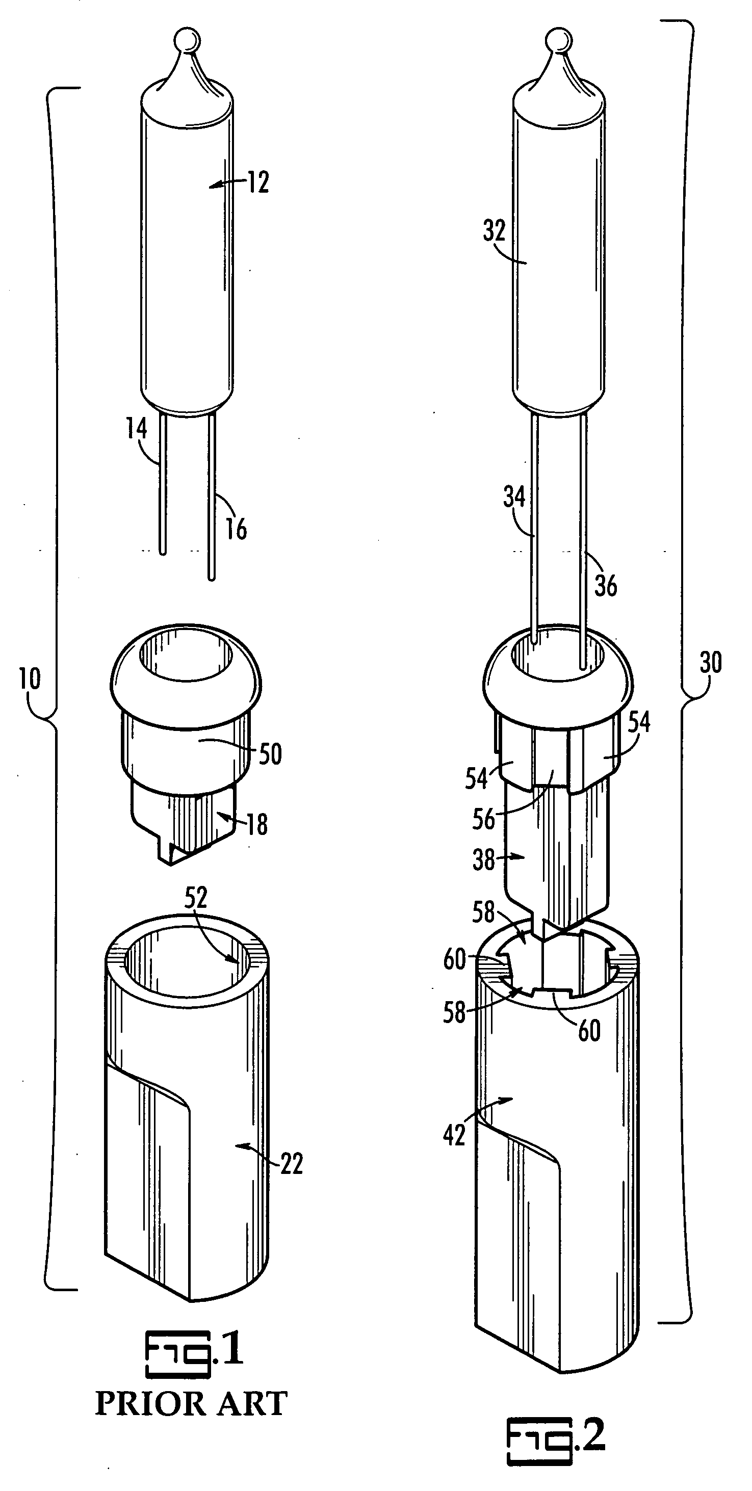
[0010] An important advantage of the present invention is that the bulb base is easily removable from the socket. Prior art bulb bases that are made to be not removable, and can invite the use of excessive force by users who try to remove them, which may result in a possible safety hazard. In the case of the present special application sockets, the lamp socket and base are not tapered but are straight, so that the base can be removed from the socket.
[0011] An important feature of the present invention is the use of a longer socket. In addition to being important to preventing a standard bulb from being operable in the present special application socket, a longer socket looks different than a standard socket and can thus be visually identified quickly.
[0012] Still another important feature of the present invention is the keying of the light base and socket to prevent twisting of one with respect to the other. Keying means that complementary patterns of slots and grooves are formed on the socket and base to make it impossible for one to be rotated with respect to the other when the base is fully seated in the socket. Second, the keying prevents the interchanging of standard bulbs and sockets with the present special application bulbs and sockets. Third, the keying helps maintain the alignment of Dumet wires with electrical contacts within the socket and prevents their misalignment when bases are inserted into sockets.
[0013] These and other features and their advantages will be apparent to those skilled in the art of light string design from a careful reading of the Detailed Description of Preferred Embodiments accompanied by the following drawings.

Problems solved by technology

If the present bulb and base are somehow forced into a standard socket, it will be clear that they are not intended to be used together because the base will not fit and will be too long for the socket.
Prior art bulb bases that are made to be not removable, and can invite the use of excessive force by users who try to remove them, which may result in a possible safety hazard.

Method used


Image

  • Special application light for light strings
  • Special application light for light strings
  • Special application light for light strings

Examples


Embodiment Construction

[0021] The present invention is a special application light. The present light has a bulb, a base and a socket. The base and bulb will only be operable in the present socket. Although the bulb and base are easily removable from the socket without undue effort, the present bulb and base cannot be twisted with respect to the present socket once seated. Furthermore, if a standard bulb and base were somehow forced into the present socket, a feat that requires considerable effort, the standard bulb and base would not function. Finally, the present socket, being longer than a standard socket, is easily visually distinguished from the standard socket.

[0022] Referring now to FIGS. 1 and 2, there is shown an exploded perspective view of a prior art light 10 in FIG. 1 and of the present light 30 in FIG. 2, according to a preferred embodiment of the present invention. These exploded perspective views highlight the differences between the prior art light and the present light.

[0023] In FIG. 1...


PUM


Abstract

A light for use in light strings has a deeper socket, a longer base and longer Dumet wires than a standard socket, base, and Dumet wires so that the standard bases and bulbs will not operate in the non-standard socket. Furthermore, the base and sockets are keyed so that they are restricted to at most two orientations with respect to each other and cannot be twisted with respect to each other.

Description

CROSS REFERENCE TO RELATED PATENTS [0001] Not applicable BACKGROUND OF THE INVENTION [0002] The present invention relates to strings of lights and, in particular, to special application lights used in strings of lights, such as fuse lights and flicker lights. In the present specification, the word light will be used to denote the combination of a bulb, bulb base (or simply “base”), and socket. [0003] Light strings such as the type used to decorate Christmas trees may include sets of 50 or 100 miniature lights arranged electrically in series. In addition to standard lights used in these sets, which meet industry standards set by Underwriters Laboratories (UL Standard 588, in particular), manufacturers have created lights that serve special functions, such as flicker or twinkle lights and fuse lights. While in some cases these special application bulbs may be used in any socket in the light string and in any number, in other cases, the manufacturer may want to limit the number of thes...

Claims


Application Information

Patent Timeline
IPC IPC(8): F21S13/14
CPCF21S8/00F21V19/0005F21W2121/04F21Y2103/025H01R33/09F21Y2103/37
Inventor GIBBONEY, JAMES W.
Owner BEST POINT GROUP
Learn More