
Information recording medium, and information recording apparatus and method

a technology of information recording and information, applied in the field of information recording medium, can solve the problems of difficult time-consuming, difficult uninterrupted reproduction, and only incorporating a huge buffer for this purpose, and achieve the effect of efficient recording, efficient recording, and efficient recording of information

Active Publication Date: 2007-04-19
PIONEER CORP
View PDF1 Cites 0 Cited by
  • Summary
  • Abstract
  • Description
  • Claims
  • Application Information

AI Technical Summary

Benefits of technology

[0008] In order to solve the above-mentioned conventional problems, it is therefore an object of the present invention to provide a multilayer type information recording medium on which test writing can be efficiently performed and the record information can be efficiently recorded, into each recording layer, and an information recording apparatus and an information recording method capable of efficiently recording the information onto such an information recording medium. Means for Solving the Object

Problems solved by technology

Thus, there is such a technical problem that uninterrupted reproduction is not easy in terms of time.
For example, if a reproduction buffer is set to be huge, it is possible to perform the uninterrupted reproduction, in changing the recording layer which is the target of such reproduction; however, it is extremely disadvantage in practice to incorporate the huge buffer only for this purpose, from the viewpoint of cost or the like.
In addition, there is also such a problem that even if record information in which interruption is allowed is recorded or reproduced, when the recording layer is actually changed, it takes an extremely long time.
Therefore, there is such a technical problem that it takes an extremely long time for the OPC process.
However, this causes such a technical problem that it takes an extremely long time in changing the recording layer during the recording operation.

Method used


Image

  • Information recording medium, and information recording apparatus and method
  • Information recording medium, and information recording apparatus and method
  • Information recording medium, and information recording apparatus and method

Examples


first example

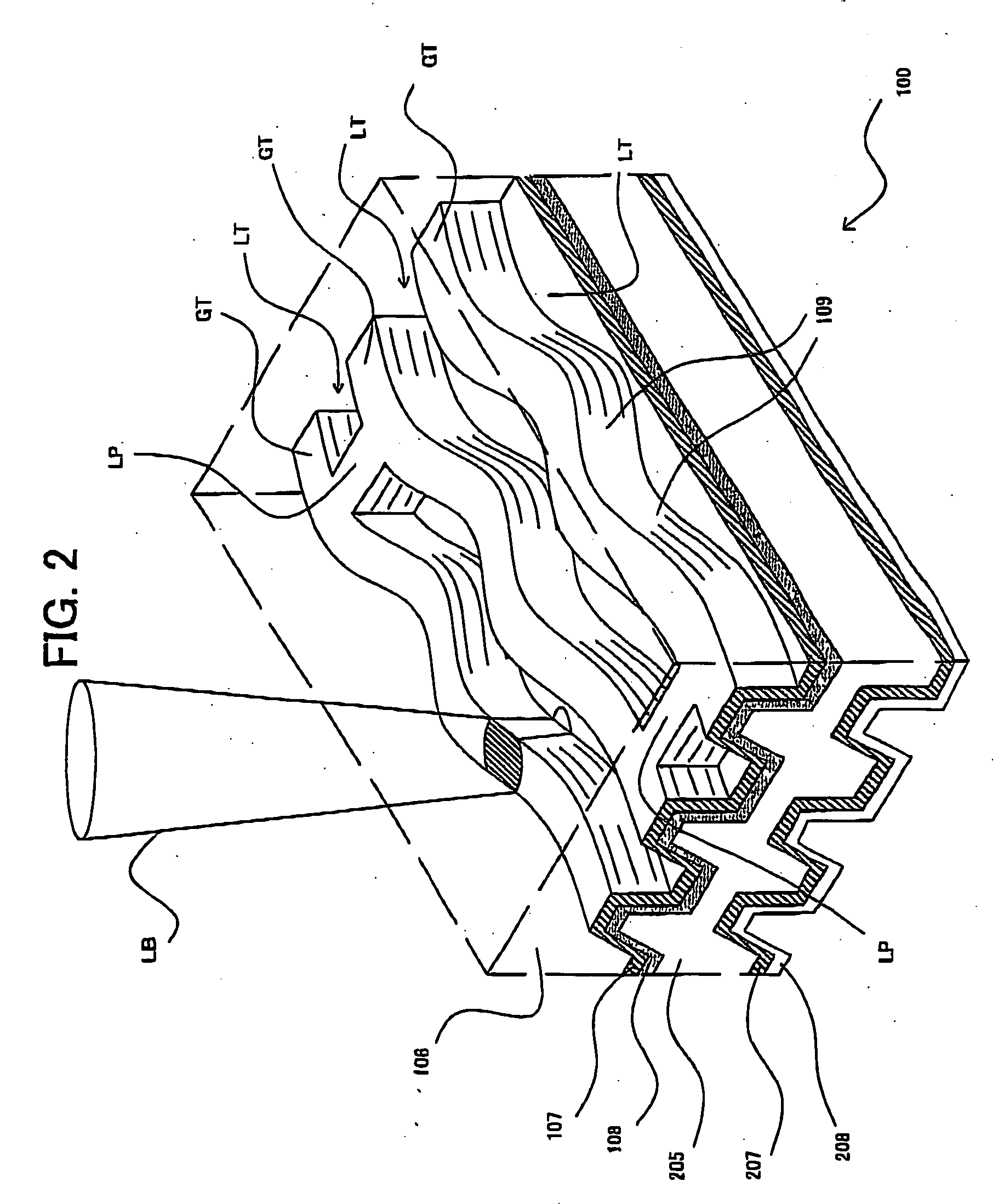
[0098] Next, with reference to FIG. 1 to FIG. 3, an optical disc according to the first example of the information recording medium will be discussed in detail.

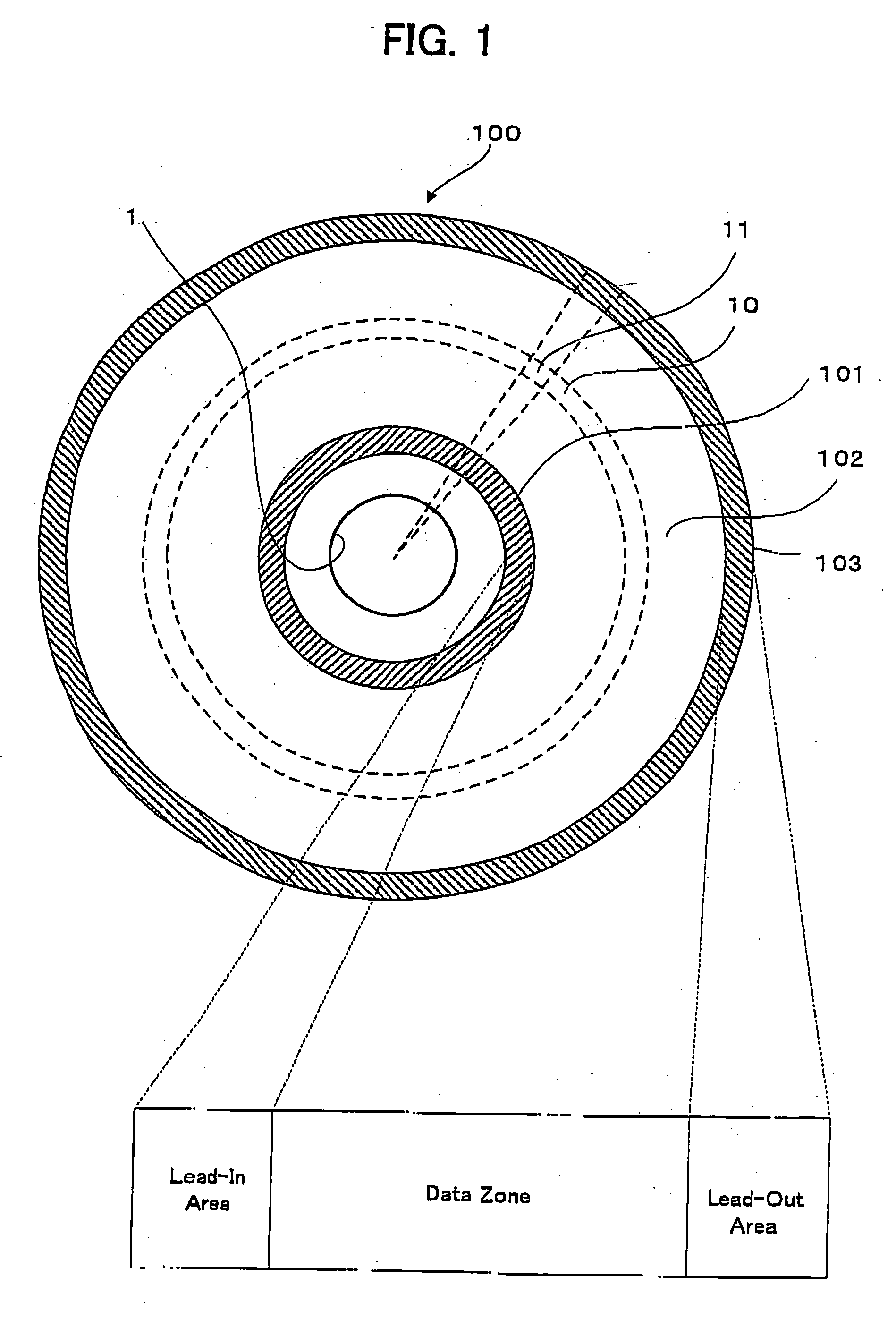
[0099] At first, with reference to FIG. 1, the basic structure of the optical disc in the first example will be discussed. FIG. 1 shows the basic structure of the optical disc according to the first example of the information recording medium of the present invention, wherein the upper part is a substantial plan view showing the optical disc having a plurality of areas and the corresponding lower part is a schematic conceptual view showing a recording area structure in the radial direction.

[0100] As shown in FIG. 1, an optical disc 100 has a recording surface on a disc main body with a diameter of about 12 cm, as is a DVD. On the recording surface, the optical disc 100 is provided with: a lead-in area 101; a data zone 102; and a lead-out area 103, which are associated with the example, from the inner circumferential side to...

second example

[0126] Next, with reference to FIG. 4, a detailed explanation will be given to the data structure of the optical disc and the area used in the OPC process, according to the second example of the information recording medium of the present invention. FIG. 4 is a data structural view conceptually showing the data structure of the optical disc and the area used in the OPC process, according to the second example of the information recording medium of the present invention.

[0127] The basic structure and the OPC process in the second example of the information recording medium are substantially the same as those in the first example, explained with reference with reference to FIG. 1 to FIG. 3.

[0128] Particularly in the second example of the information recording medium, an unrecordable area 101U-1 is provided in the L0 layer, which constitutes one example of the “space area” of the present invention, in addition to the areas of the first example.

[0129] Specifically, in the unrecordabl...

third example

[0130] Next, with reference to FIG. 5, a detailed explanation will be given to the data structure of the optical disc and the area used in the OPC process, according to the third example of the information recording medium of the present invention. FIG. 5 is a data structural view conceptually showing the data structure of the optical disc and the area used in the OPC process, present invention. FIG. 6 is a data structural view conceptually showing the data structure of the optical disc and the area used in the OPC process, according to the fourth example of the information recording medium of the present invention.

[0131] The basic structure and the OPC process in the fourth example of the information recording medium are substantially the same as those in the first example, explained with reference with reference to FIG. 1 to FIG. 3.

[0132] Particularly in the fourth example of the information recording medium, the power calibration area 101P-1 of the L0 layer and the power calibr...


PUM

PropertyMeasurementUnit
diameteraaaaaaaaaa
areaaaaaaaaaaa
sizeaaaaaaaaaa

Abstract

A disc-shaped information recording medium includes a first recording layer (L0 layer) having (I) a first trial write area (101P-1) for trial write of first trial write information for calibration of the laser beam along the first track path (TP1) from the inner circumference toward the outer circumference and (II) a first recording area for recording the first recording information along a first track path (TP1), in this order from the inner circumference side. Furthermore, the disc-shaped information recording medium includes a second recording layer (L1 layer) having (I) a second trial write area (101P-2) for trial write of second trial write information for calibration of the laser beam along the second track path (TP2) from the outer circumference toward the inner circumference and (II) a second recording area for recording the second recording information along a second track path (TP2), in this order from the inner circumference side.

Description

TECHNICAL FIELD [0001] The present invention relates to an information recording medium, such as a DVD, and an information recording apparatus, such as a DVD recorder, an information recording method. BACKGROUND ART [0002] For example, in the information recording medium, such as a CD and a DVD, as described in patent documents 1 and 2 or the like, there are developed a multiple layer or multilayer type, or dual layer type optical disc and so on, in which a plurality of recording layers are laminated or stacked on the same substrate. Then, in the information recording apparatus, such as a CD recorder, for recording information onto such a dual layer type (i.e. two-layer type) optical disc, the information is recorded into a recording layer (referred to as a “L0 layer” in this application, as occasion demands), located on the front or the closest side as viewed from the emission or irradiation side of laser light, in a rewritable method or irreversible change recording method by irre...

Claims


Application Information

Patent Timeline
Patent Type & Authority Applications(United States)
IPC IPC(8): G11B7/12G11B7/00G11B7/0045G11B7/007G11B7/125G11B7/1267G11B7/24
CPCG11B7/0045G11B7/00736Y10T428/21G11B7/24038G11B2007/0013G11B7/1267G11B7/007
Inventor MURAMATSU, EIJITANIGUCHI, SHOJIHORIKAWA, KUNIHIKOKATO, MASAHIROSUZUKI, TOSHIOKURODA, KAZUO
Owner PIONEER CORP
Learn More