
Magnetic recording and reproducing device and magnetic recording medium

a recording and reproducing device technology, applied in the direction of instruments, metal sheet core heads, disposition/mounting of heads, etc., can solve the problems of difficult to precisely magnetize only a target portion of the magnetic recording layer, hard to apply a stronger magnetic field, and difficult to precisely record and delete magnetic data, etc., to achieve improved increase the density of areal density, and improve the effect of recording and reproducing precision

Inactive Publication Date: 2005-09-01
TDK CORPARATION
View PDF7 Cites 24 Cited by
  • Summary
  • Abstract
  • Description
  • Claims
  • Application Information

AI Technical Summary

Benefits of technology

The present invention provides a magnetic recording and reproducing device that achieves both high areal density and good recording and reproducing precision. This is achieved by a magnetic recording medium with a concavo-convex pattern formed by convex portions of a predetermined track width and an effective recording area created by a heating head and a recording head. The effective recording width is equal to or more than the track width and a sum of the track width and the doubled value of width of concave portions between the tracks. The invention also provides a magnetic recording medium with a filling material that has lower heat conductivity than the magnetic recording layer. The invention also suppresses problems such as side fringe and cross-talk, leading to increased areal density.

Problems solved by technology

As the increase in the areal density leads to thermal instability, it is preferable to use material that has high magnetic anisotropy, which exhibits high coercivity, for the magnetic recording layer; however, with conventional magnetic heads, it was hard to apply a stronger magnetic field than the coercivity of such a high magnetic anisotropy material, i.e., recording and deleting of magnetic data were hard to achieve.
With this method, however, it was hard to precisely magnetize only a target portion of the magnetic recording layer, because the peripheral part of the portion to which electron beam is projected is also heated by heat conduction, and because the temperature distribution of the heated portion and the magnetic field distribution of the magnetic head are not uniform.

Method used


Image

  • Magnetic recording and reproducing device and magnetic recording medium
  • Magnetic recording and reproducing device and magnetic recording medium
  • Magnetic recording and reproducing device and magnetic recording medium

Examples


Embodiment Construction

[0044] Various exemplary embodiments of this invention will be hereinafter described in detail with reference to the drawings.

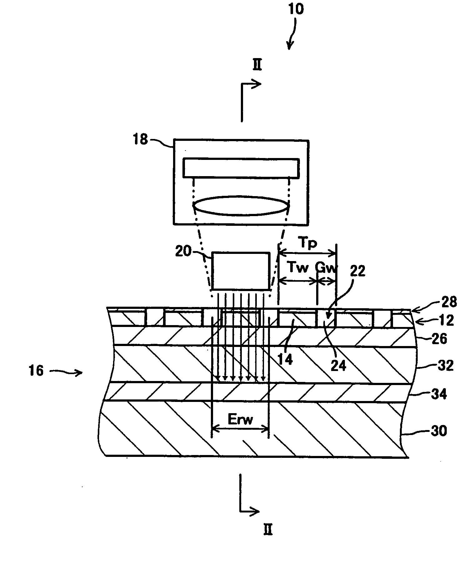
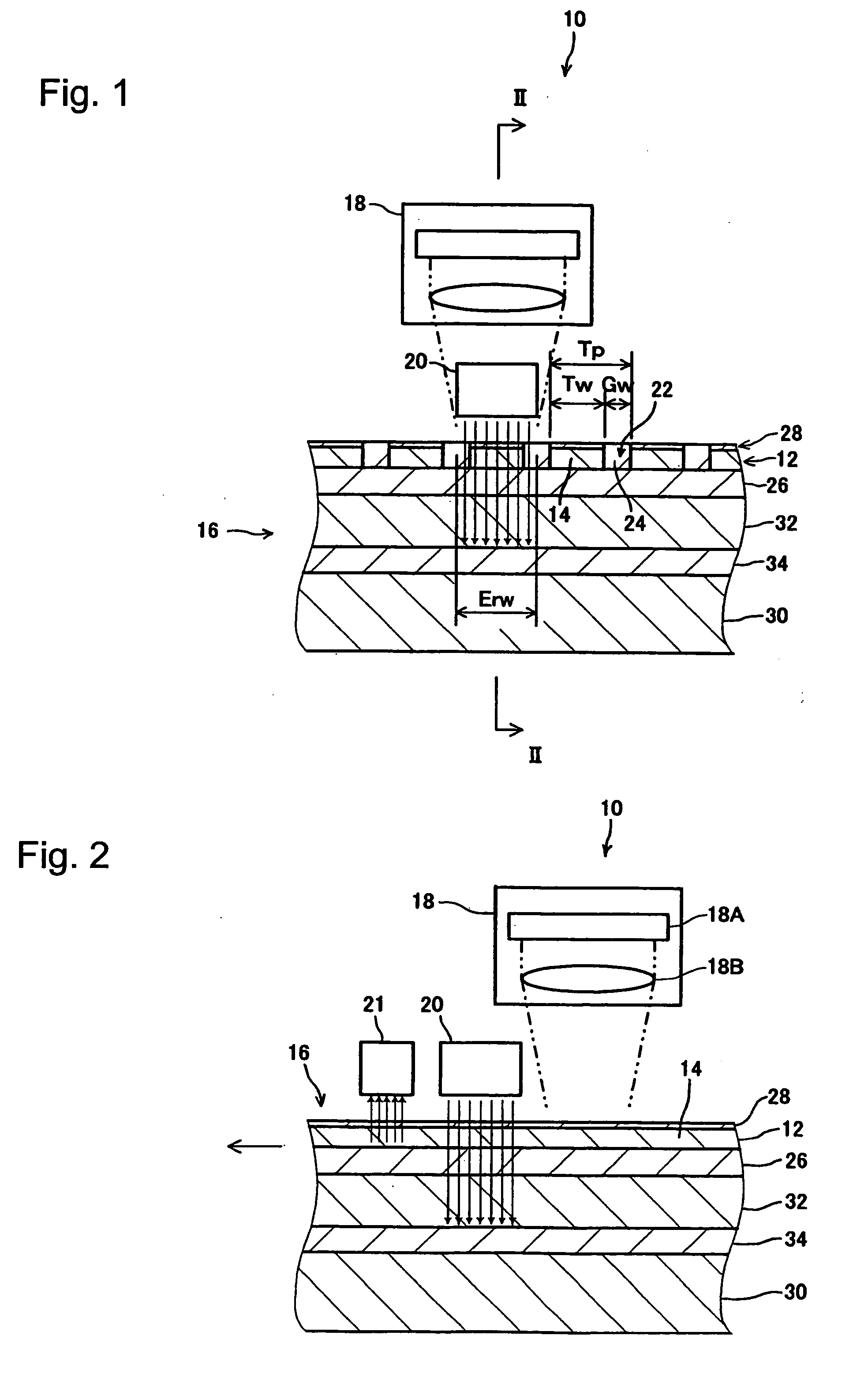
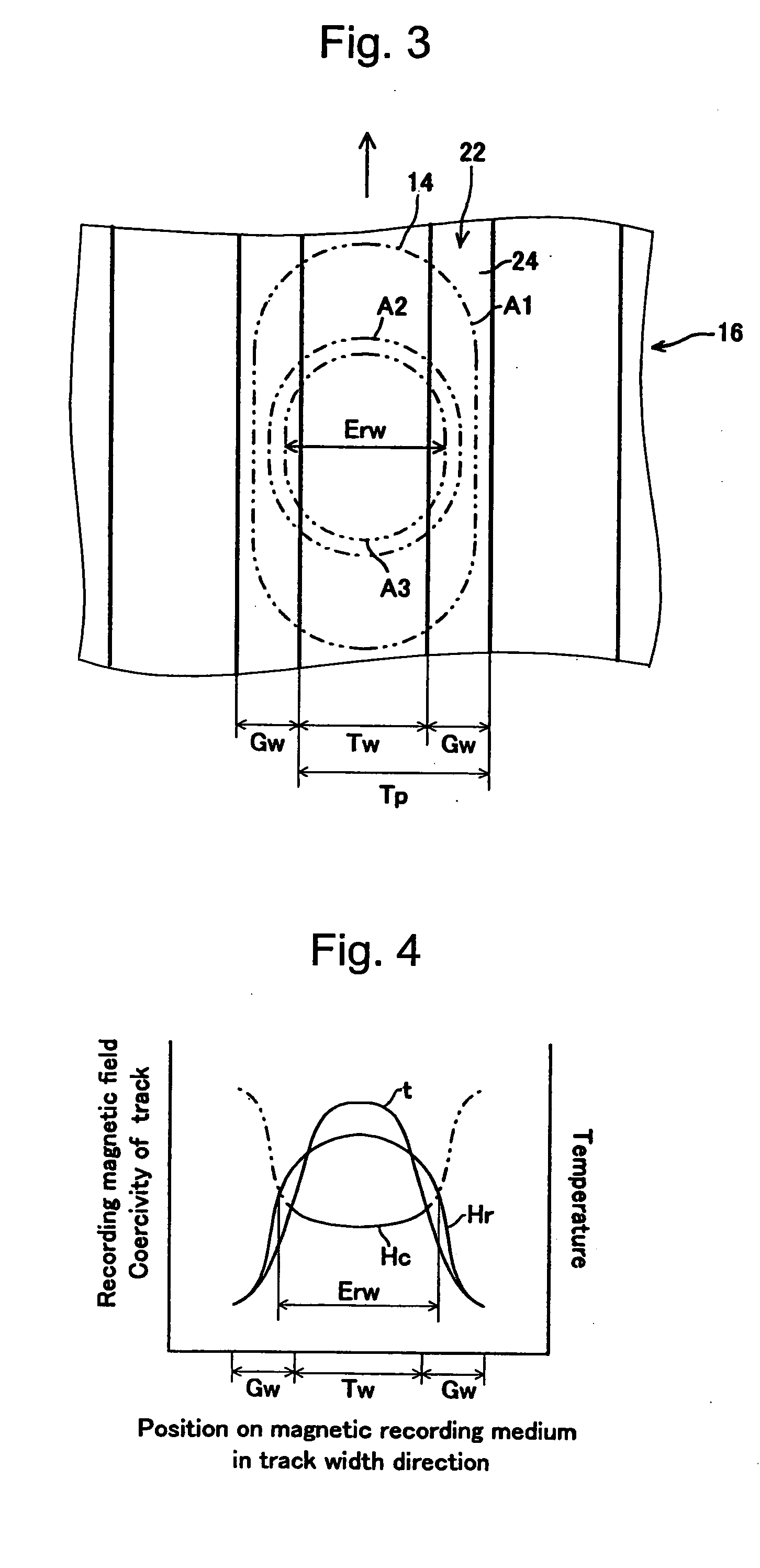
[0045] As shown in FIG. 1 to FIG. 4, a magnetic recording and reproducing device 10 according to a first exemplary embodiment of the present invention includes a magnetic recording medium 16 having a magnetic recording layer 12 formed in a concavo-convex pattern so that tracks 14 for recording magnetic data are formed by convex portions of a predetermined track width Tw and arranged in parallel with a predetermined track pitch Tp in the track width Tw direction, a heating head 18 for heating the magnetic recording medium 16 to partially reduce the coercivity of the tracks 14, a recording head 20 for applying a recording magnetic field to a heated portion of the magnetic recording medium 16, and a reproducing head 21 for detecting a reproducing magnetic field on the tracks 14. An effective recording area A3 created on the magnetic recording medium 16 by the h...


PUM

PropertyMeasurementUnit
widthaaaaaaaaaa
coercivityaaaaaaaaaa
recording magnetic fieldaaaaaaaaaa

Abstract

A magnetic recording and reproducing device includes: a magnetic recording medium in which a magnetic recording layer is formed in a concavo-convex pattern so that tracks are formed by convex portions of a predetermined track width and arranged in parallel in the track width direction; a heating head for heating the magnetic recording medium to partially reduce coercivity of the tracks; a recording head for applying a recording magnetic field to a heated portion of the magnetic recording medium to record magnetic data on the tracks; and a reproducing head for detecting a reproducing magnetic field of the tracks. In this configuration, an effective recording area has an effective recording width that is equal to or more than the track width, and equal to or less than a sum of the track width and a doubled value of width of concave portions between the tracks.

Description

BACKGROUND OF THE INVENTION [0001] 1. Field of the Invention [0002] The present invention relates to a magnetic recording and reproducing device which records magnetic data by application of heat and magnetic field and magnetically reproduces the magnetic data, and to a magnetic recording medium. [0003] 2. Description of the Related Art [0004] There has been a remarkable increase in areal density of magnetic recording media such as hard discs by various improvements including reduction in the grain size of magnetic particles forming the magnetic recording layer, material changes, and increased precision in the processing of magnetic heads, and a further improvement in the areal density is expected. [0005] As the increase in the areal density leads to thermal instability, it is preferable to use material that has high magnetic anisotropy, which exhibits high coercivity, for the magnetic recording layer; however, with conventional magnetic heads, it was hard to apply a stronger magnet...

Claims


Application Information

Patent Timeline
Patent Type & Authority Applications(United States)
IPC IPC(8): G11B5/65G11B5/00G11B5/012G11B5/02G11B5/147G11B5/62G11B5/64G11B5/72G11B5/738G11B5/74G11B5/855G11B7/08G11B7/085G11B7/09G11B11/00G11B11/10
CPCB82Y10/00G11B5/012G11B5/65G11B5/74G11B5/743G11B2005/0029G11B2005/0002G11B2005/0005G11B2005/001G11B2005/0021G11B5/855
Inventor HATTORI, KAZUHIROSOENO, YOSHIKAZUTAKAI, MITSURUOKAWA, SHUICHI
Owner TDK CORPARATION
Learn More