Magnetic recording medium and method of manufacturing magnetic recording medium

a magnetic recording medium and recording medium technology, applied in the direction of maintaining head carrier alignment, instruments, applications, etc., can solve the problems of low productivity of the servo information recording process, low accuracy of information recording/reading, flying height and orientation of the head, etc., to achieve stable head behavior and efficient recording of servo information

Inactive Publication Date: 2007-01-16
TDK CORPARATION
View PDF18 Cites 24 Cited by
  • Summary
  • Abstract
  • Description
  • Claims
  • Application Information

AI Technical Summary

Benefits of technology

[0011]In view of the foregoing problems, various exemplary embodiments of this invention provide a magnetic recording medium which serves for stable head behavior and efficient recording of servo information. Further more, various exemplary embodiments of the invention provide a method of manufacturing such a magnetic recording medium.
[0015]Note that the servo pattern gap filling parts / part are / is formed as part of the magnetic layer 12, and thus are easy to fabricate as compared to the case where the servo pattern gap filling parts / part are / is made of other materials. This is advantageous in terms of productivity.

Problems solved by technology

The process of recording the servo information has a problem of low productivity since servo pattern parts of the servo areas and the peripheral parts thereof are magnetized in opposite polarities one by one for every magnetic recording medium by a servo track writing method.
Nevertheless, if servo patterns are made of recesses and projections, the airflow between the magnetic recording medium and the head is disturbed to make the flying height and orientation of the head unstable, causing the problem of a drop in information recording / read accuracy.
In particular, many servo patterns have certain regularities, which can often contribute to unstable airflow between the magnetic recording medium and the head.
Servo patterns are determined depending on disc drives on the head side, and it is therefore impossible to adopt arbitrary servo patterns for stabilizing the airflow between the magnetic recording medium and the head.
Consequently, the head flying height and the head orientation tend to be unstable across the boundaries between the servo areas and the data areas in particular.

Method used


Image

  • Magnetic recording medium and method of manufacturing magnetic recording medium
  • Magnetic recording medium and method of manufacturing magnetic recording medium
  • Magnetic recording medium and method of manufacturing magnetic recording medium

Examples


example

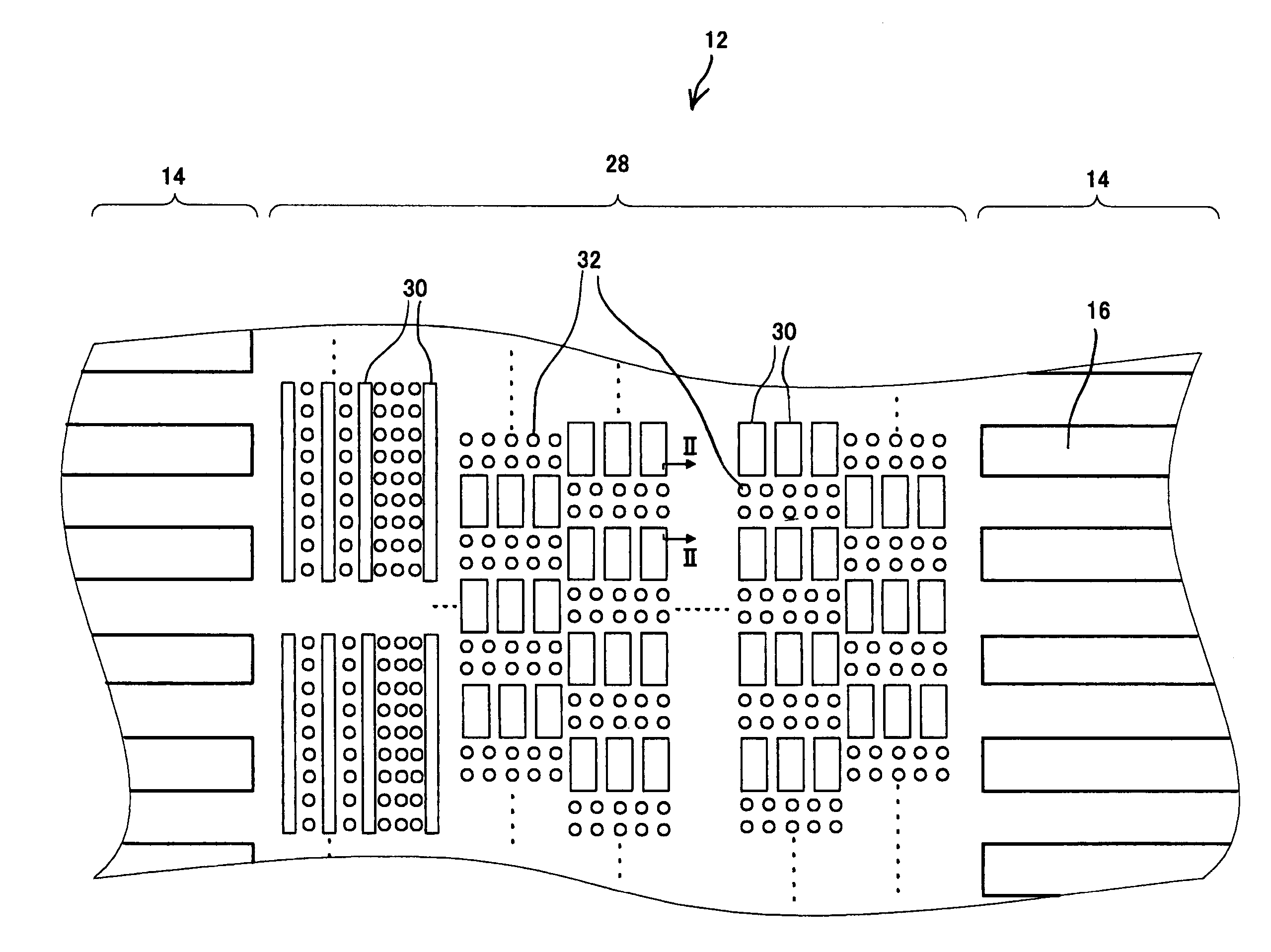
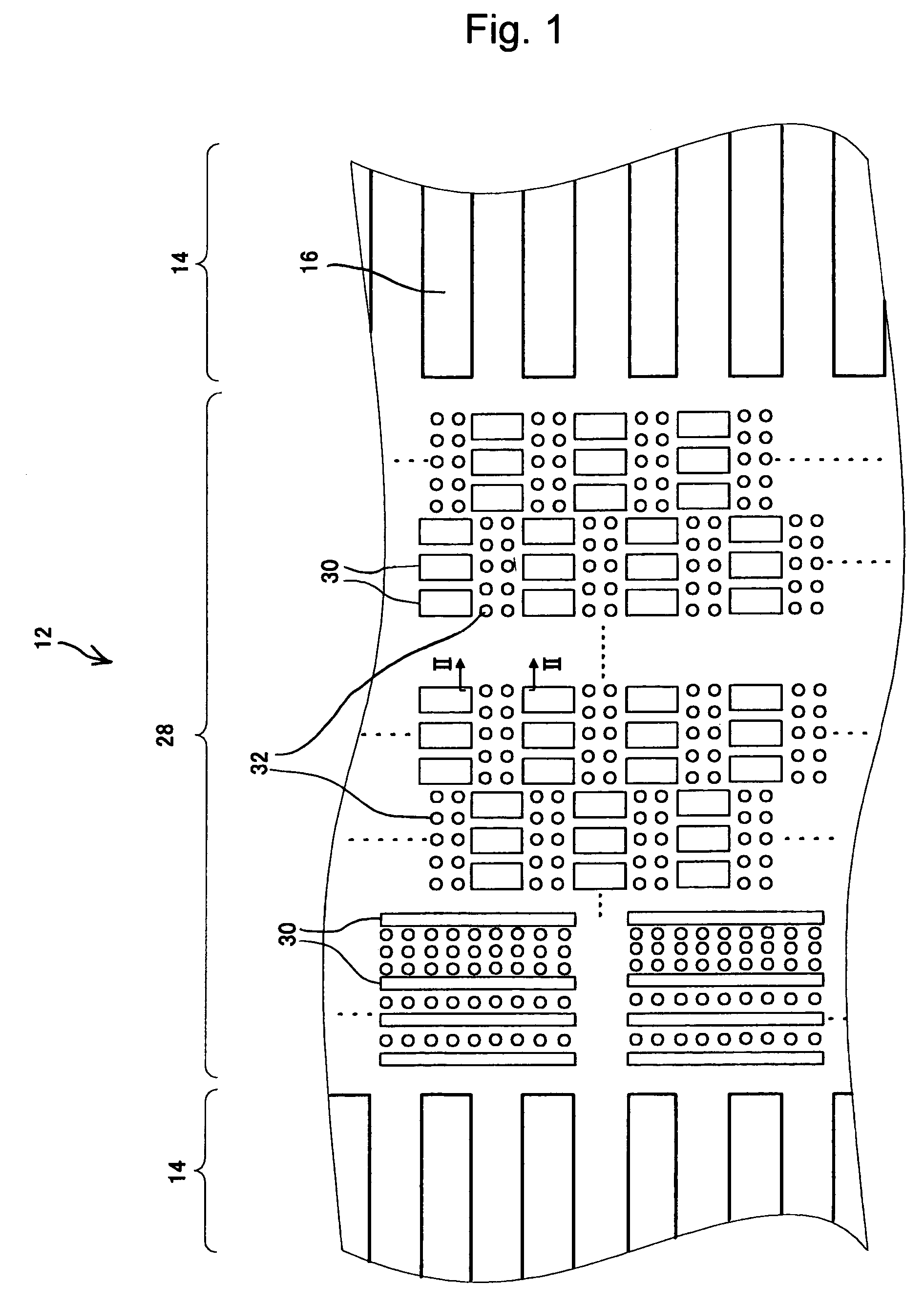
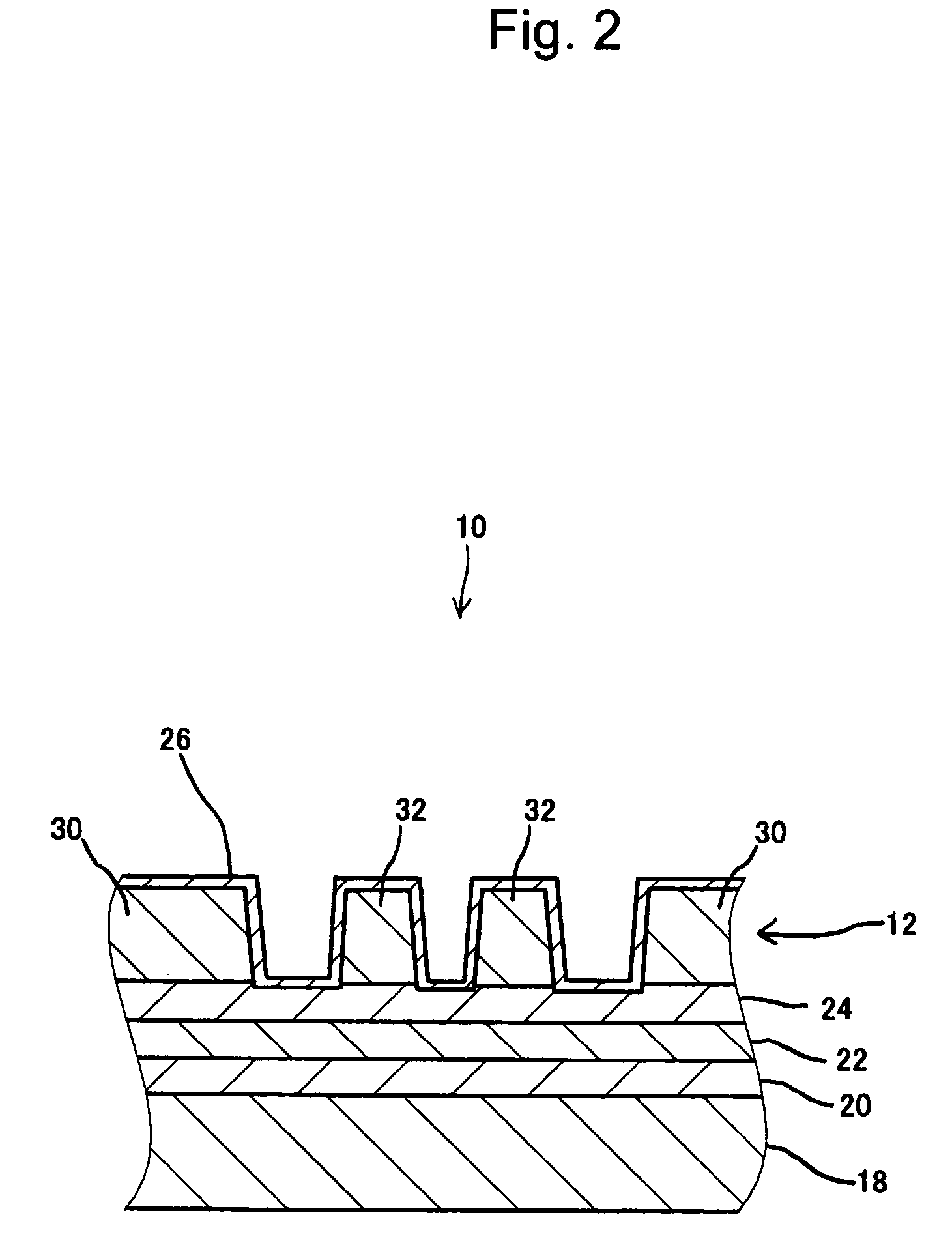
[0087]A magnetic recording medium 10 was fabricated according to the foregoing exemplary embodiment. The servo pattern gap filling parts 32 were formed in a generally circular shape of approximately 100 nm in diameter.

[0088]The magnetic recording medium 10 was rotated with a head slider (not shown) in the vicinity, and the flying height of the head element was measured. The head element behaved as shown by the curve designated by the symbol C in FIG. 13. Incidentally, the portion where the curve varies greatly shows the variation in the flying height of the head element across the boundary between a data area and a servo area. The flying height of the head element was stable within the data area. The head element showed a variation of 0.5 nm after the head slider entered the servo area. A maximum variation of approximately 1.9 nm was observed at the instant when the head element of the head slider entered from the data area into the servo area.


PUM

PropertyMeasurementUnit
lengthaaaaaaaaaa
sizesaaaaaaaaaa
widthaaaaaaaaaa

Abstract

A magnetic recording medium and a method of manufacturing the same which serve for stable head behavior and efficient recording of servo information. In each servo area, a magnetic layer is separated into a plurality of servo pattern unit parts for forming a predetermined servo pattern and a plurality of servo pattern gap filling parts patterned to fill gaps between the plurality of servo pattern unit parts partly. The servo pattern unit parts and the servo pattern gap filling parts are formed in different sizes so as to have different magnetic properties.

Description

BACKGROUND OF THE INVENTION[0001]1. Field of the Invention[0002]The present invention relates to a magnetic recording medium and a method of manufacturing a magnetic recording medium.[0003]2. Description of the Related Art[0004]Conventionally, magnetic recording media such as a hard disc have magnetic layer which is sectioned into a plurality of data areas and a plurality of servo areas for information recording. Servo information intended for control such as head positioning is magnetically recorded on the servo areas in a predetermined servo pattern.[0005]The process of recording the servo information has a problem of low productivity since servo pattern parts of the servo areas and the peripheral parts thereof are magnetized in opposite polarities one by one for every magnetic recording medium by a servo track writing method. In particular, with a recent improvement in surface recording density and an accompanying decrease in head flying height, high-density high-precision record...

Claims


Application Information

Patent Timeline
Patent Type & Authority Patents(United States)
IPC IPC(8): G11B5/09G11B5/82G11B5/012G11B5/596G11B5/65G11B5/667G11B5/74G11B5/84G11B5/852G11B5/855G11B11/105
CPCB82Y10/00G11B5/59633G11B5/74G11B5/852G11B5/855G11B5/743G11B11/10584G11B11/10578A62B17/04A41D13/1153
Inventor HATTORI, KAZUHIROITO, KUNIYASU
Owner TDK CORPARATION
Why Eureka
Try Eureka