Storage system and storage control method

Inactive Publication Date: 2007-04-26
HITACHI LTD
View PDF4 Cites 43 Cited by
  • Summary
  • Abstract
  • Description
  • Claims
  • Application Information

AI Technical Summary

Benefits of technology

[0019] In a second aspect of the present invention, the above-mentioned first storage subsystem can send the above-mentioned first information, the above-mentioned difference data group, and the above-mentioned second information, in that order, to the above-mentioned second storage subsystem. The above-mentioned second storage subsystem can create a journal group, which represents the order of the above-mentioned first information, the above-mentioned difference journal group, and the above-mentioned second information. The above-mentioned third storage subsystem, based on the above-mentioned journal group, can recognize th

Problems solved by technology

However, the problem is that requiring a user to perform a complicated operation in

Method used


Image

  • Storage system and storage control method
  • Storage system and storage control method
  • Storage system and storage control method

Examples


Embodiment Construction

[0034] A storage system related to one embodiment of the present invention will be explained below using the FIGS.

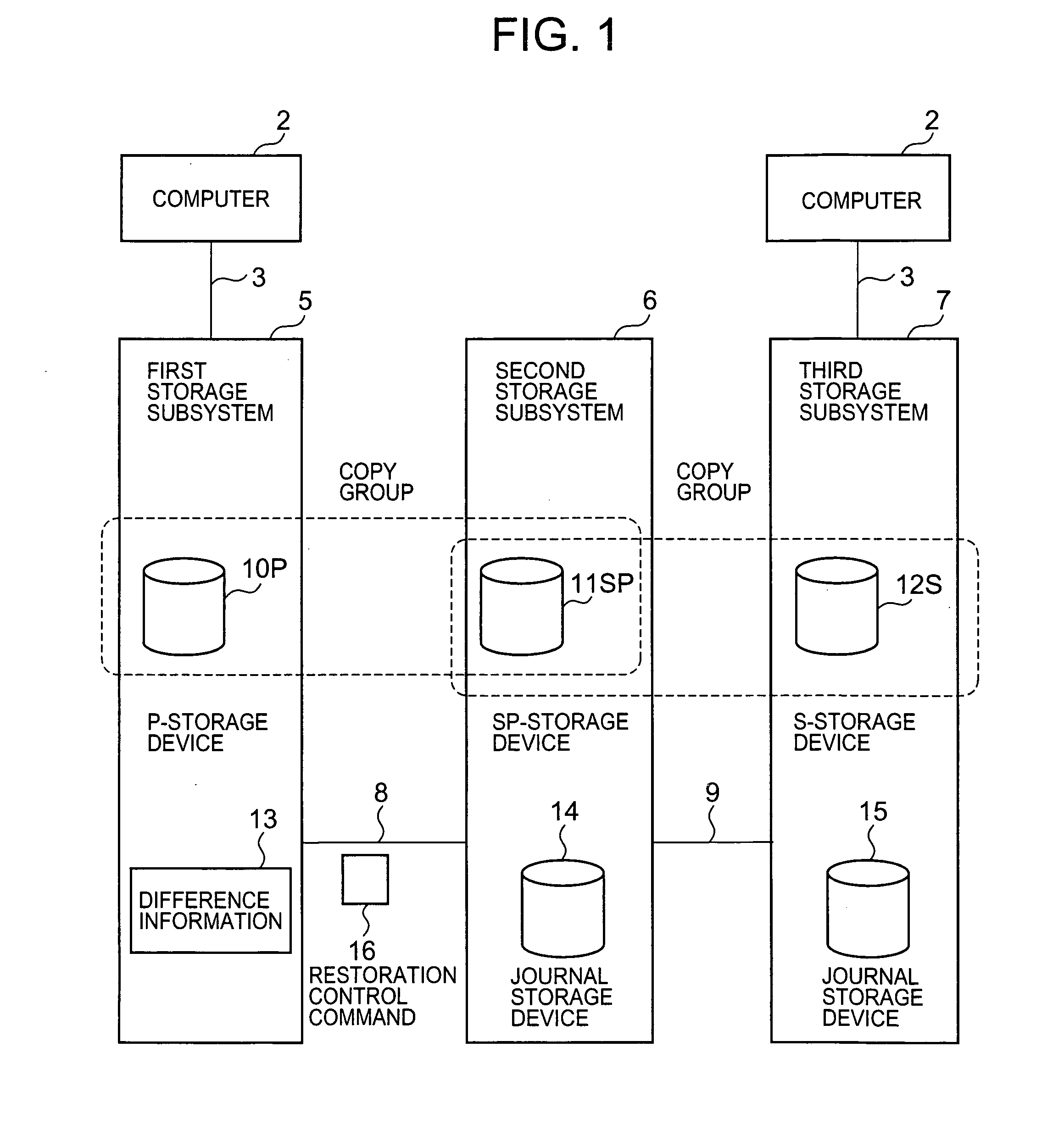
[0035]FIG. 1 is a diagram showing an overview of a storage system related to one embodiment of the present invention.

[0036] A storage system related to this embodiment comprises a first storage subsystem 5, a second storage subsystem 6, and a third storage subsystem 7. A computer 1 is communicatively connected to the first storage subsystem 5 via a path 3, and the second storage subsystem 6 is communicatively connected to the first storage subsystem 5 via a path 8. The third storage subsystem 7 is communicatively connected to the second storage subsystem 6 via a path 9. A computer 2 is communicatively connected to the third storage subsystem 7 via a path 4. The paths 3, 8, 9, and 4 can be provided by dedicated lines and communications networks. Further, the respective computers 1, 2 can be communicatively connected to all of the storage subsystems 5 through 7.

[0037] T...


PUM


Abstract

The present invention, when an external device accesses a third storage device in a prescribed environment, increases the likelihood of data in the third storage device being updated in the order in which data in a first storage device is updated, without the need for complex operations by a user.
More specifically, when difference information 13 comprising a data group, which represents differences between a data group inside a P-storage device 10P and a data group inside an SP-storage device 11SP, is transmitted, a first storage subsystem 5 sends an interrupt command and a restart command such that the difference information 13 is interposed therebetween, and a third storage subsystem 7 receives the interrupt command and restart command by way of a second storage subsystem 6, and based on these commands, writes the data group inside the difference information 13 to an S-storage device 12S.

Description

CROSS-REFERENCE TO PRIOR APPLICATION [0001] This application relates to and claims priority from Japanese Patent Application No. 2005-309286, filed on Oct. 25, 2005 the entire disclosure of which is incorporated herein by reference. BACKGROUND OF THE INVENTION [0002] 1. Field of the Invention [0003] The present invention relates to storage control technology, and more particularly to the restoration of data using remote copying. [0004] 2. Description of the Related Art [0005] A storage system comprising a plurality of storage subsystems is known. As such a storage system, for example, there is the system disclosed in Japanese Laid-open Patent No. 2003-122509. In Japanese Laid-open Patent No. 2003-122509, for example, the following is disclosed. [0006] (1) A first storage subsystem is connected to a second storage subsystem, and the second storage subsystem is connected to a third storage subsystem. Synchronous-type remote copying is carried out between the first storage subsystem an...

Claims


Application Information

Patent Timeline
IPC IPC(8): G06F13/00
CPCG06F11/1451G06F11/2058G06F11/2064G06F11/2071G06F2201/855
Inventor MATSUI, YOSHINORIMAKI, NOBUHIRO
Owner HITACHI LTD
Why Eureka
Try Eureka