Wind resistant magnetic letter holders for large signs

a magnetic letter and letter holder technology, applied in the field of wind resistance magnetic letter holders for large signs, can solve the problem that one cannot get a screw driver to fit behind the letter, and achieve the effect of convenient alignmen

Inactive Publication Date: 2007-05-03
UNIVERSAL MEDIA SYST
View PDF13 Cites 2 Cited by
  • Summary
  • Abstract
  • Description
  • Claims
  • Application Information

AI Technical Summary

Benefits of technology

The patent text is saying that the letters are easy to align, meaning they can be positioned easily.

Problems solved by technology

The technical problem addressed in this patent text is the traditional way of making signs that use halo lit channel letters. These signs require unsightly fasteners and electric wires to be visible between the letters, which can make the sign look bad. Additionally, these signs are vulnerable to high winds and flying debris.

Method used


Image

  • Wind resistant magnetic letter holders for large signs
  • Wind resistant magnetic letter holders for large signs
  • Wind resistant magnetic letter holders for large signs

Examples


Embodiment Construction

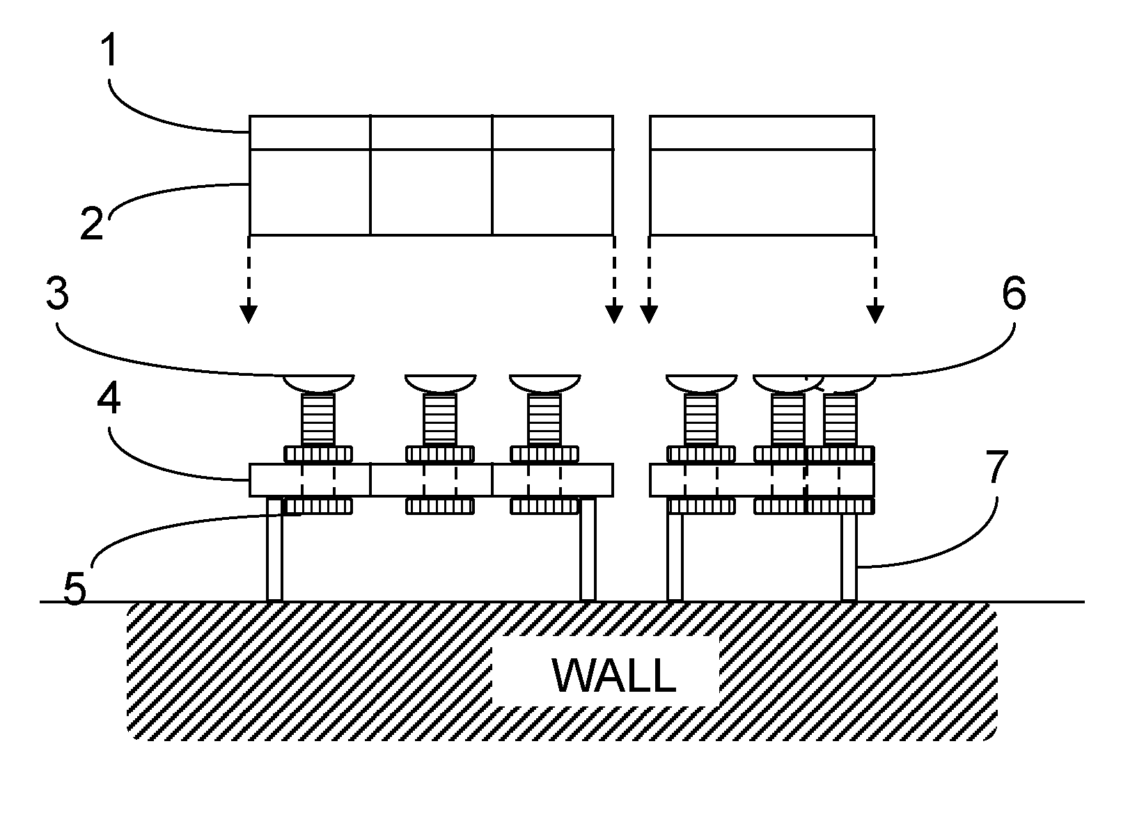
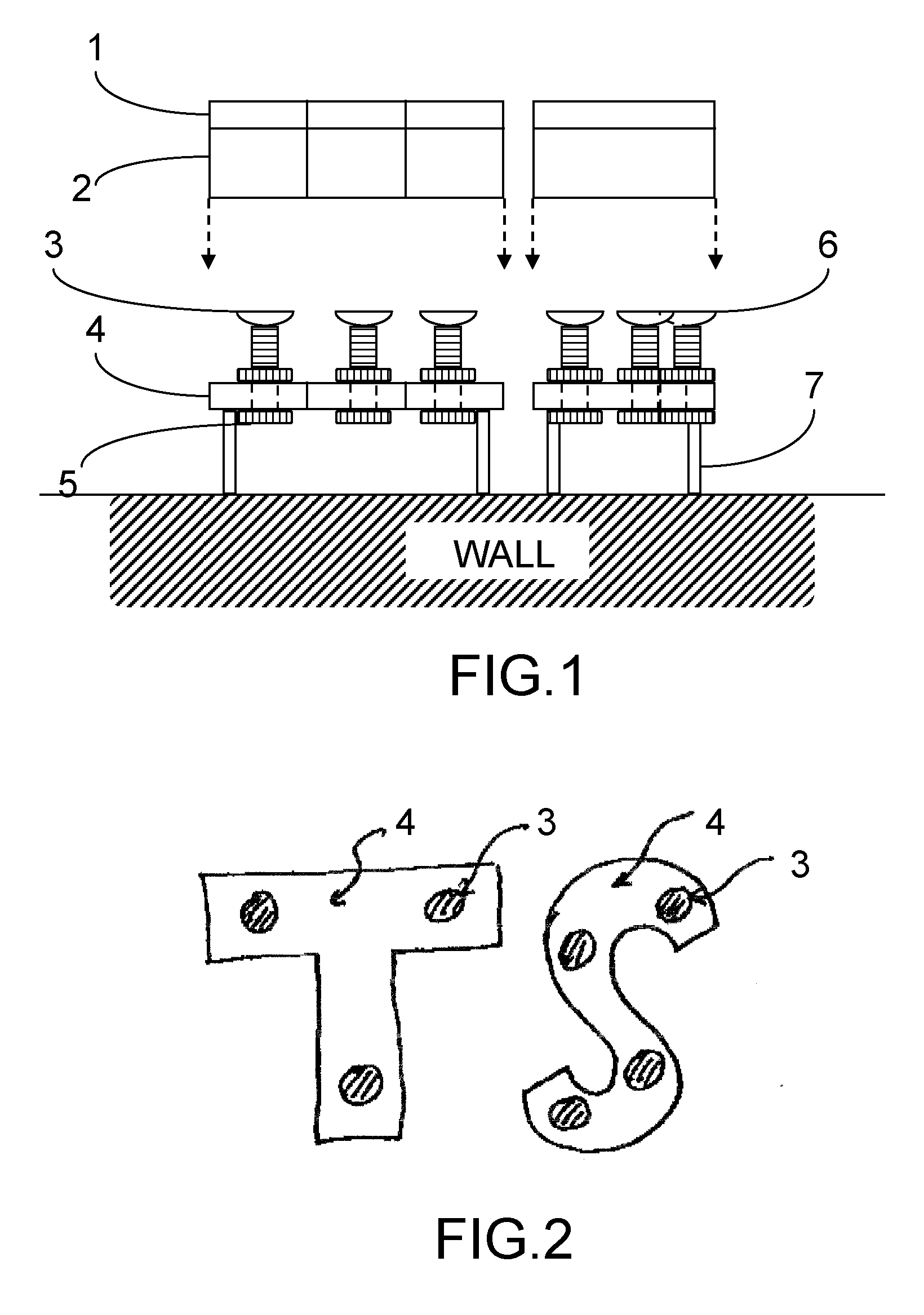
[0011] The drawings in FIGS. 1 and 2 have the following numeric designations: [0012] 1. A galvanized sheet of metal that is glued to the letter's inside surface. This is not required if the letter itself is magnetic. [0013] 2. The letter [0014] 3. Magnetic heads [0015] 4. The mounting plate upon which the letter is mounted. [0016] 5. Bolts to hold the magnets to the mounting plate. [0017] 6. Magnets holding letter to the mounting plate. [0018] 7. Fasteners

[0019] In order to hide exposed side fasteners on a decorative letter, magnets 6 are mounted on the mounting plate 4 using standard fasteners 7 that hold the mounting plate to the wall. The magnets 6 comprise magnetic heads 3. The letter 2 is magnetically attached to the mounting plate by positioning the galvanized sheet 1 over the mounting plate so as to hold the assembly together with no exposed fasteners. The mounting plate 4 is smaller than the letter 2. The letter can be adjusted or realigned if the mounting plate 4 was place...


PUM


Abstract

A magnetic holder for letters appearing on a wall sign. A typical application would be for signs requiring halo glow lighting. With such a sign, the letter itself is unlit, and the wall is lit by soft lighting from behind the letter. Lighting could be accomplished with the use of a plurality of light emitting diodes (LED). The Present Invention comprises a mounting plate that is securely attached to the wall. The LED's, lighting circuitry, and magnets are securely fastened to the mounting plate. The letter is a hollow magnetic channel letter that is slightly larger than the mounting plate. The letter is positioned over the mounting plate, and is held in position by the magnets. The letter may be manually positioned on the plate for proper alignment.

Description


Claims


Application Information

Patent Timeline
Owner UNIVERSAL MEDIA SYST
Why Eureka
Try Eureka