Apparatus and methods for inspecting a composite structure for defects

a composite structure and inspection apparatus technology, applied in the field of automatic material placement machines, can solve the problems of limited effectiveness of current inspection systems when used to inspect materials, and achieve the effect of reducing the number of inspections

Active Publication Date: 2007-05-03
THE BOEING CO
View PDF74 Cites 37 Cited by
  • Summary
  • Abstract
  • Description
  • Claims
  • Application Information

AI Technical Summary

Problems solved by technology

Current inspection systems, however, have limited effectiveness when used to inspect materials wider than about six inches.

Method used


Image

  • Apparatus and methods for inspecting a composite structure for defects
  • Apparatus and methods for inspecting a composite structure for defects
  • Apparatus and methods for inspecting a composite structure for defects

Examples


Embodiment Construction

[0016] The following description of various embodiments is merely exemplary in nature and is in no way intended to limit the invention, its application, or uses.

[0017] In some implementations, the invention is directed to systems and methods of inspecting material laid by a material placement machine. The placement machine could be, for example, a multi-head tape lamination machine (MHTLM), a fiber placement (FP) machine, or a contour tape lamination (CTL) machine. It should be noted that implementations of the invention may be practiced in connection with a wide variety of material placement machines and processes.

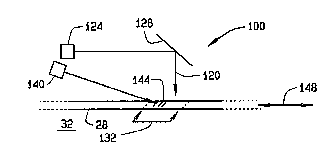
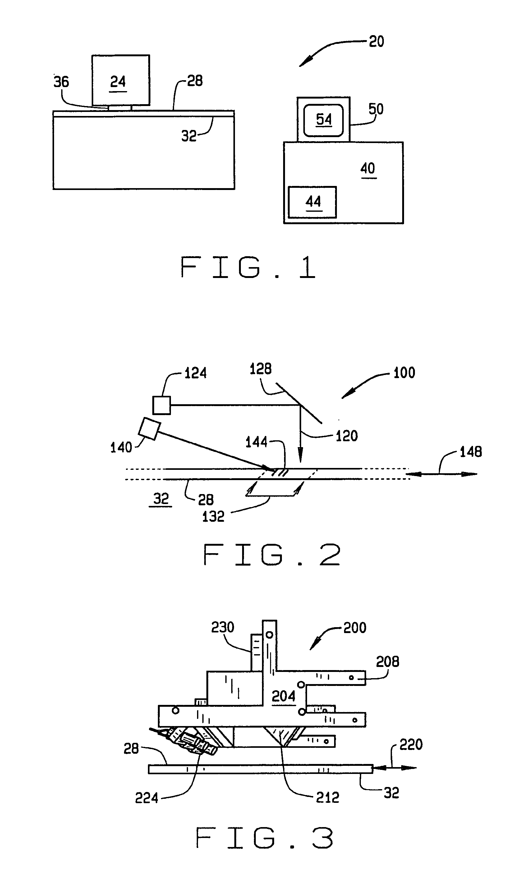
[0018] A block diagram of an exemplary material placement system is indicated generally in FIG. 1 by reference number 20. A material placement machine 24 is used to lay down composite material 28 onto a substrate 32 to fabricate a composite structure. The machine 24 includes a roller, compaction shoe and / or other component, numbered as 36 and dependent on the type of pl...


PUM

PropertyMeasurementUnit
widthsaaaaaaaaaa
widthsaaaaaaaaaa
angleaaaaaaaaaa

Abstract

A system and method of inspecting material laid by a material placement machine. Light is directed onto the material in a direction essentially normal to the material to illuminate a section of the material. Laser energy is projected onto the section at an angle predetermined to reveal imperfections in the section. This system provides improved illumination for material widths exceeding six inches and is scalable for inspecting various material widths.

Description

FIELD OF THE INVENTION [0001] The present invention relates generally to automated material placement machines and their use. More particularly (but not exclusively) the present invention relates to systems and methods for inspecting material laid by an automated material placement machine. BACKGROUND OF THE INVENTION [0002] Automated material placement processes and machines are widely used in aerospace and other industries in the fabrication of large composite structures. Systems are available by which automated visual inspection can be performed while the material is being laid. These systems have been shown to be effective in reducing machine down-time for inspection purposes. Current inspection systems, however, have limited effectiveness when used to inspect materials wider than about six inches. SUMMARY OF THE INVENTION [0003] The present invention, in one aspect, is directed to a method of inspecting material laid by a material placement machine. Light is directed onto the m...

Claims


Application Information

Patent Timeline
Patent Type & Authority Applications(United States)
IPC IPC(8): G01N21/00
CPCB29C70/382B29C70/386G01N21/88G01N2021/8472G01N2021/8867G01N2201/0635G01N2201/0636
Inventor ENGELBART, ROGER W.HANNEBAUM, REEDPOLLOCK, TIMORR, SAMPUTNAM, JEFFRECTOR, ERIC
Owner THE BOEING CO
Why Eureka
Try Eureka