

Image forming apparatus
- Summary
- Abstract
- Description
- Claims
- Application Information
AI Technical Summary
Benefits of technology
Problems solved by technology
Method used
Image

Examples
embodiment 1
[Embodiment 1]
[0022] Hereinafter, the image forming apparatus in accordance with the present invention will be described in more detail with reference to the appended drawings.
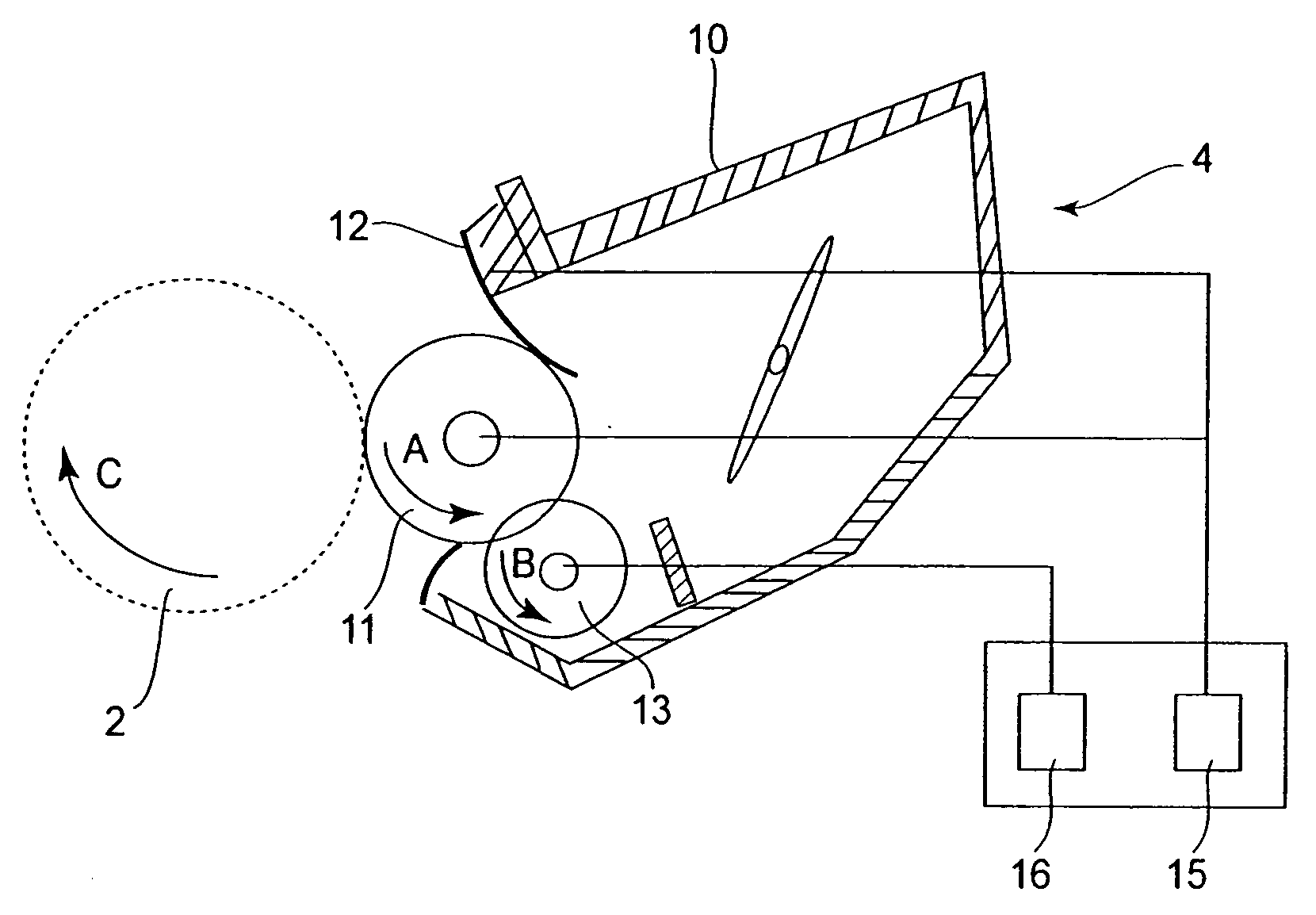
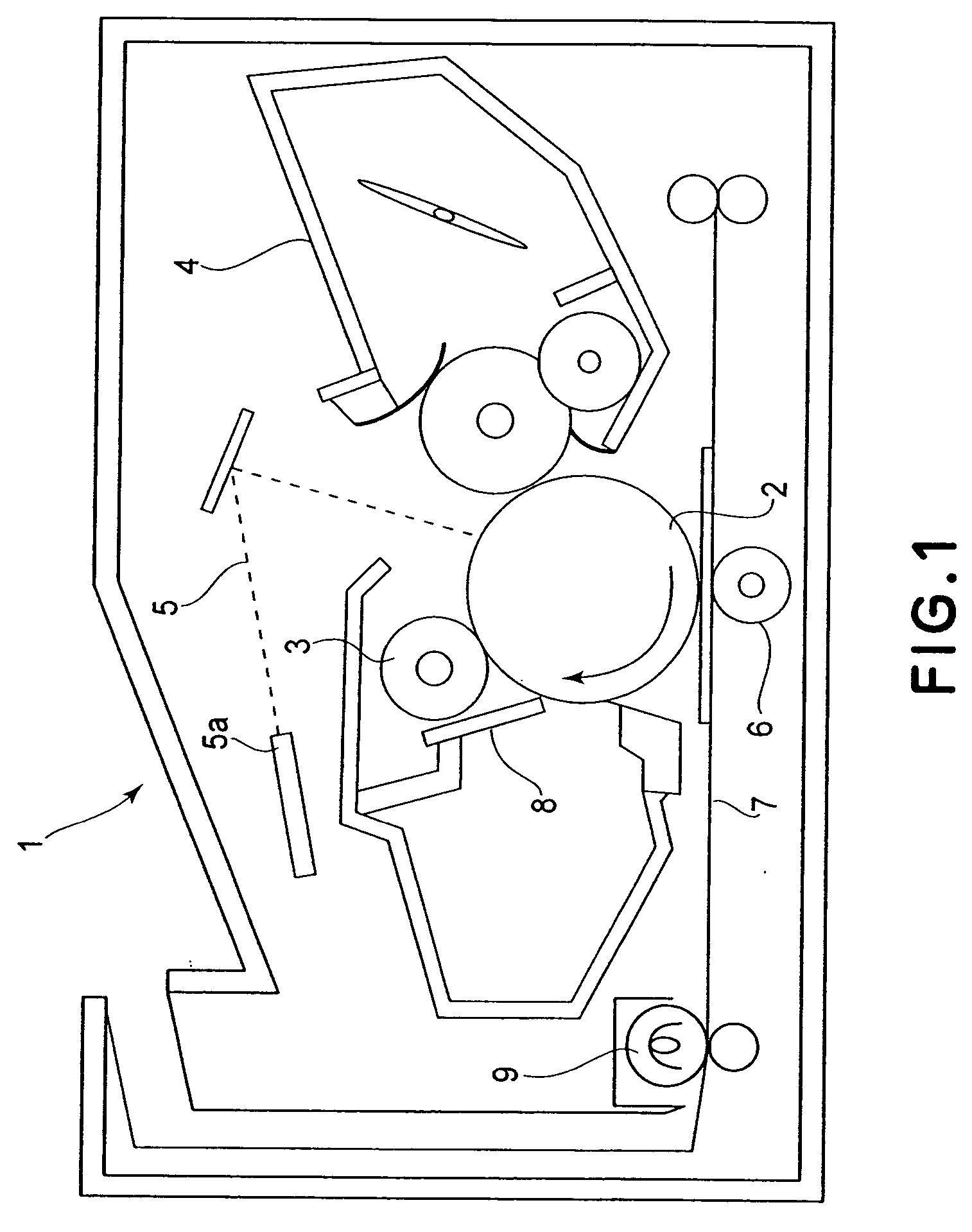
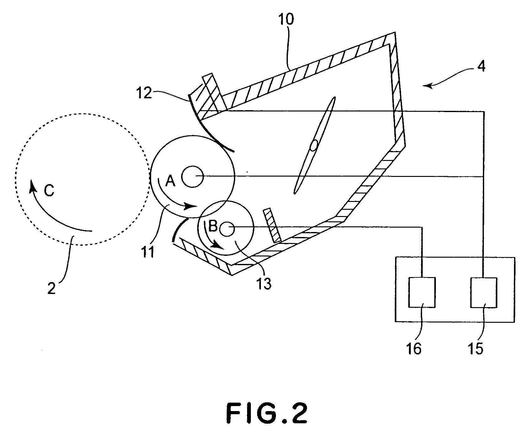
[0023]FIG. 1 is a schematic sectional view of the image forming apparatus in accordance with the present invention, and FIG. 2 is a schematic sectional view of the developing apparatus employed by the image forming apparatus.
[0024] First, referring to FIG. 1, the general structure and operation of the image forming apparatus 1 structured in accordance with the present invention will be described.
[0025] The image forming apparatus 1 in this embodiment is a laser beam printer which forms an image on a sheet of transfer medium (recording paper, OHP sheet, fabric, etc.) with the use of an electrophotographic image forming method, and outputs the sheet of transfer medium. More specifically, it forms an image on the recording medium, in response to picture information signals from a picture information source, su...
embodiment 2
[Embodiment 2]
[0045] Next, referring to FIG. 3, the developing apparatus employed by an image forming apparatus, in another preferred embodiment of the present invention will be described. The basic structure and operation of the developing apparatus and image forming apparatus in this embodiment are roughly the same as those in the first preferred embodiment. Therefore, an element of the apparatuses in this embodiment, which is practically the same in function and structure as, or equivalent in function and structure to, the one in the first embodiment is given the same referential symbol as the one given to describe the first embodiment, and will not be described in detail. This embodiment is different from the first embodiment in that a roller, the arithmetic average roughness Ra (JIS B 0601-1994) of which satisfies the following mathematical expression, in which Ra [μm] and X [μm] stand for the average roughness Ra of the development roller 11 and the volume average particle dia...
experiment 1
[Experiment 1]
[0060] In light of the results in the first to third comparative embodiments, it was thought to scrape away the fog formation toner by setting the ratio of the peripheral velocity of the development drum 11 relative to that of the photosensitive drum 2 to 120% at which frictional force works between the development roller 11 and photosensitive drum 2, and increasing the amount by which toner is coated on the development roller 11 while being controlled by the regulation blade 12 in order to deal with the fog problem and to achieve a satisfactory level of “solid black density”.
[0061] In this experiment, the toner was 6 μm in volume average particle diameter, and the ratio of the peripheral velocity of the development roller 11 relative to that of the photosensitive drum 2 was 120%. FIG. 6 is a graph showing the relationships among the average roughness Ra of the development roller 11, which was varied in a range of 0.1 μm-3.5 μm, the amount of the fog generation toner ...
PUM
 Abstract
Description
Claims
Application Information