Putter head

a technology of putter head and putter head, which is applied in the field of putter head, can solve the problems of difficult to grasp the distance of the putt, dull hitting sound,

Inactive Publication Date: 2007-05-03
BRIDGESTONE SPORTS
View PDF5 Cites 16 Cited by
  • Summary
  • Abstract
  • Description
  • Claims
  • Application Information

AI Technical Summary

Benefits of technology

[0017] According to the putter head in accordance with the invention, the hitting sensation at the time of hitting a ball is soft, and the hitting sound is hard, so that the sense of distance is easy to grasp.

Problems solved by technology

However, with the conventional putter head with the face insert fitted in the head body, while the hitting sensation can be made soft by the face insert, the hitting sound becomes dull (low), so that there have been cases where it is difficult to grasp a sense of distance of the putt.

Method used


Image

  • Putter head
  • Putter head
  • Putter head

Examples


first embodiment

(First Embodiment)

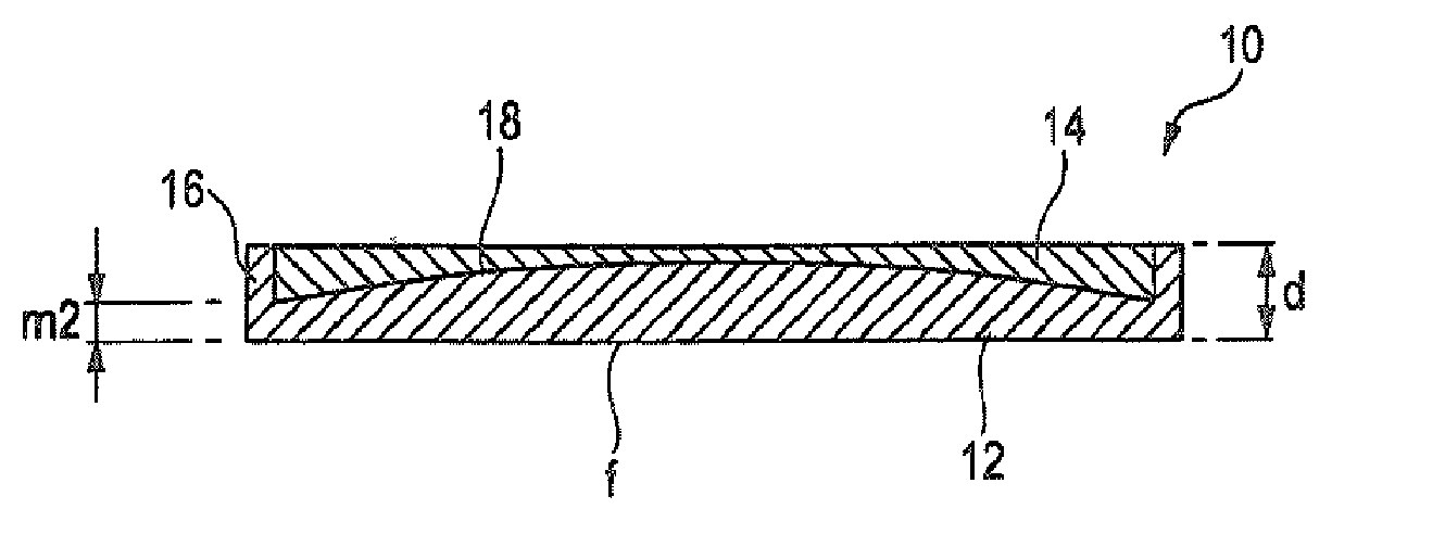
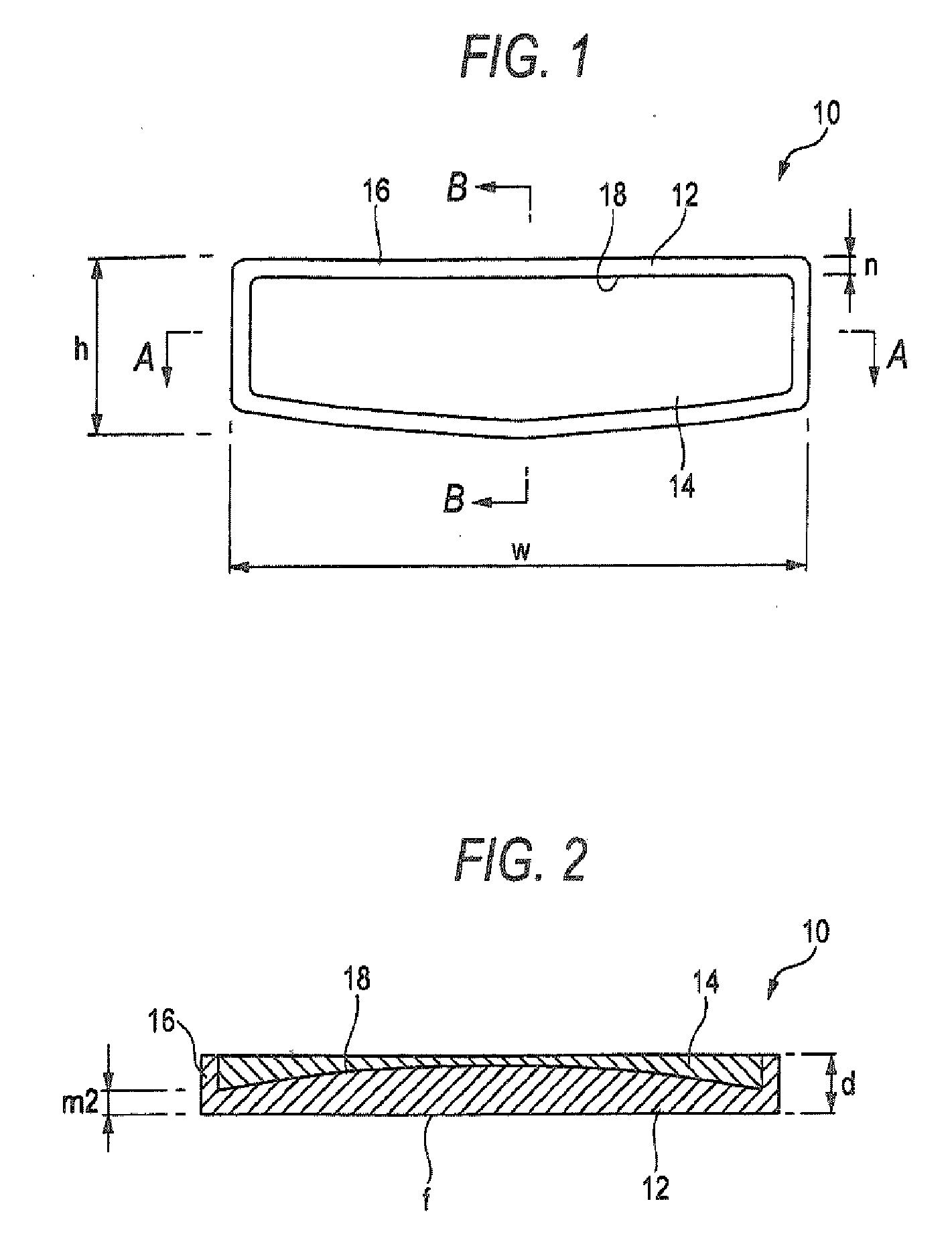
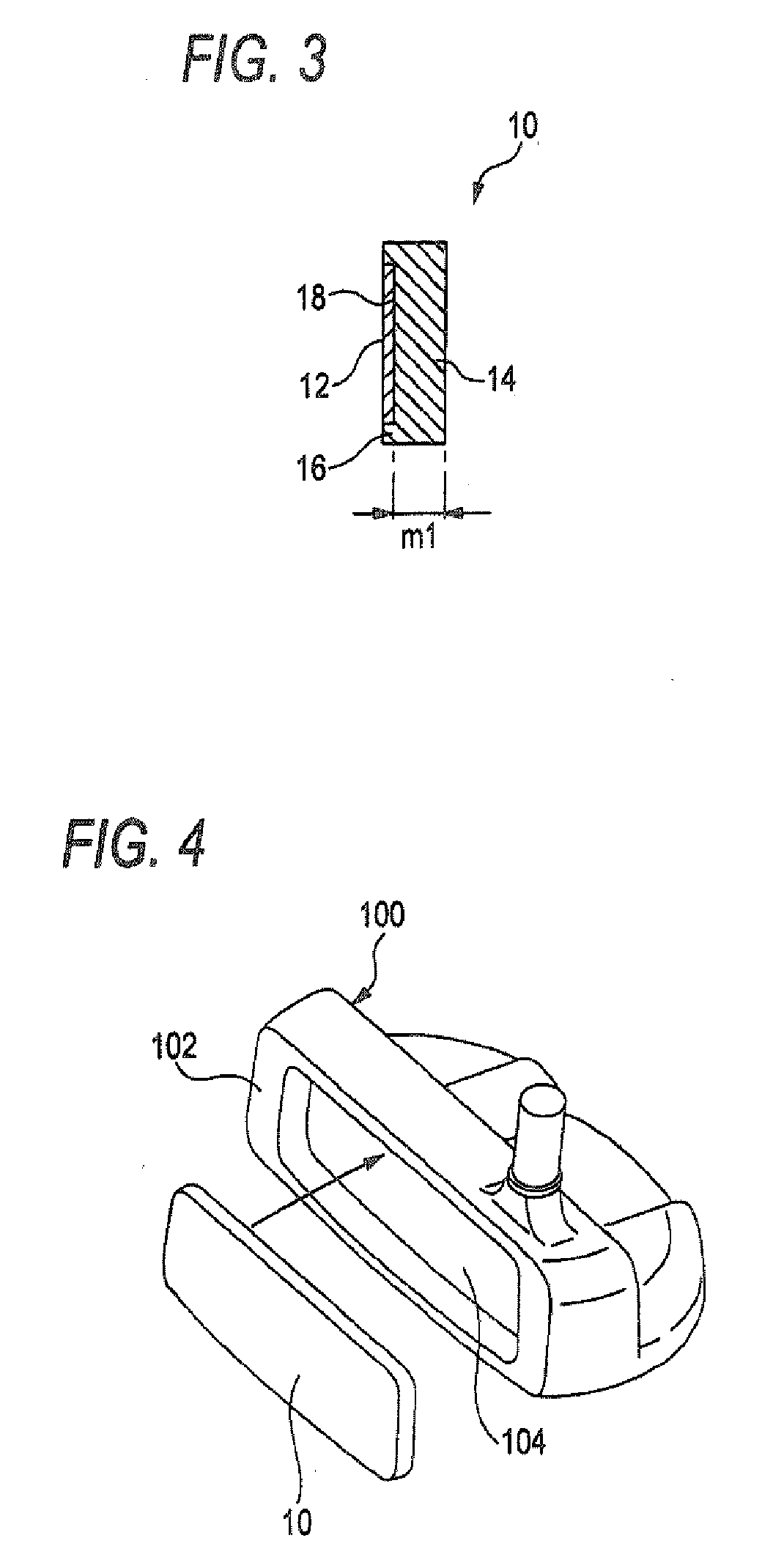
[0030]FIG. 1 is a rear view illustrating a face insert used in a putter head according to a first embodiment of the invention. FIG. 2 is a cross-sectional view taken along line A-A in FIG. 1. FIG. 3 is a cross-sectional view taken along line B-B in FIG. 1. A face insert l0 in accordance with this embodiment includes a high-hardness portion 12 that forms a hitting surface and a low-hardness portion 14 that is joined to an inner surface of the high-hardness portion l2. The hardness of the low-hardness portion 14 is lower than that of the high-hardness portion 12. In addition, in the face insert 10 of this embodiment, the thickness of the high-hardness portion 12 becomes gradually smaller from a central portion toward a peripheral portion in the longitudinal cross section shown in FIG. 2. It should be noted that the thickness of the high-hardness portion 12 is fixed in the transverse cross section shown in FIG. 3. Furthermore, in the face insert 10 of this embodiment,...

second embodiment

(Second Embodiment)

[0031]FIG. 5 is a rear view illustrating a face insert used in a putter head according to a second embodiment of the invention. FIG. 6 is a cross-sectional view taken along line A-A in FIG. 5. FIG. 7 is a cross-sectional view taken along line B-B in FIG. 5. A face insert 20 in accordance with this embodiment is similar to the first embodiment except that the frame-like body is not projectingly provided on the peripheral edges of the high-hardness portion 12. In FIGS. 5 to 7, the same component portions as those shown in FIGS. 1 to 3 are denoted by the same reference numerals, and a description thereof will be omitted. The use of the face insert 20 in accordance with this embodiment is similar to that of the first embodiment.

third embodiment

(Third Embodiment)

[0032]FIG. 8 is a longitudinal cross-sectional view illustrating a face insert used in a putter head according to a third embodiment of the invention. FIG. 9 is a transverse cross-sectional view taken along line B-B in FIG. 8. It should be noted that a rear view is the same as FIG. 1. A face insert 30 in accordance with this embodiment includes a high-hardness portion 32 that forms a hitting surface and a low-hardness portion 34 that is joined to the inner surface of the high-hardness portion 32. The hardness of the low-hardness portion 34 is lower than that of the high-hardness portion 32. In addition, in the face insert 30 of this embodiment, the thickness of the high-hardness portion 32 becomes gradually larger from the central portion toward the peripheral portion in the longitudinal cross section shown in FIG. 8. It should be noted that the thickness of the high-hardness portion 32 is fixed in the transverse cross section shown in FIG. 9. Furthermore, in the f...


PUM


Abstract

A putter head that includes: a head body having a face portion; and a face insert fitted in the face portion of a head body, the face insert including: a high-hardness portion that forms a hitting surface, and a low-hardness portion jointed to the high-hardness portion and having a hardness lower than that of the high-hardness portion. A thickness of the high-hardness portion is decreased or increased from a central portion toward a peripheral portion.

Description

BACKGROUND OF THE INVENTION [0001] 1. Field of the Invention [0002] The present invention relates to a putter head with a face insert fitted in a face portion of a head body. [0003] 2. Description of the Related Art [0004] Conventionally, a putter head has been proposed in which a face insert made of a material different from that of a head body is fitted in a face portion of the head body. For example, JP-A-2004-236985 discloses a putter head in which a face insert having a layered structure integrally including a rubber elastic body layer, a sintered metal layer, and a fluororesin layer is fitted in the face portion of the head body. In addition, JP-A-2005-124730 discloses a putter head in which an elastic body-made face insert whose thickness increases gradually from the side of the vicinity of a sweet spot of the head toward a peripheral edge side is fitted in a face portion of a head body. SUMMARY OF THE INVENTION [0005] The above-described putter head with the face insert fitt...

Claims


Application Information

Patent Timeline
Patent Type & Authority Applications(United States)
IPC IPC(8): A63B53/00A63B53/04A63B102/32
CPCA63B53/0487A63B2053/0416A63B2053/0425A63B2053/0462A63B53/0425A63B53/0462A63B53/0416
Inventor TATENO, ATSUO
Owner BRIDGESTONE SPORTS
Why Eureka
Try Eureka