Electronic thermometer with sensor location

Inactive Publication Date: 2007-05-03
COVIDIEN AG
View PDF85 Cites 30 Cited by
  • Summary
  • Abstract
  • Description
  • Claims
  • Application Information

AI Technical Summary

Problems solved by technology

However, before the adhesive is brought into contact with the components and/or before the adhesive sets, the components may undesirably move.
The

Method used


Image

  • Electronic thermometer with sensor location
  • Electronic thermometer with sensor location
  • Electronic thermometer with sensor location

Examples


first embodiment

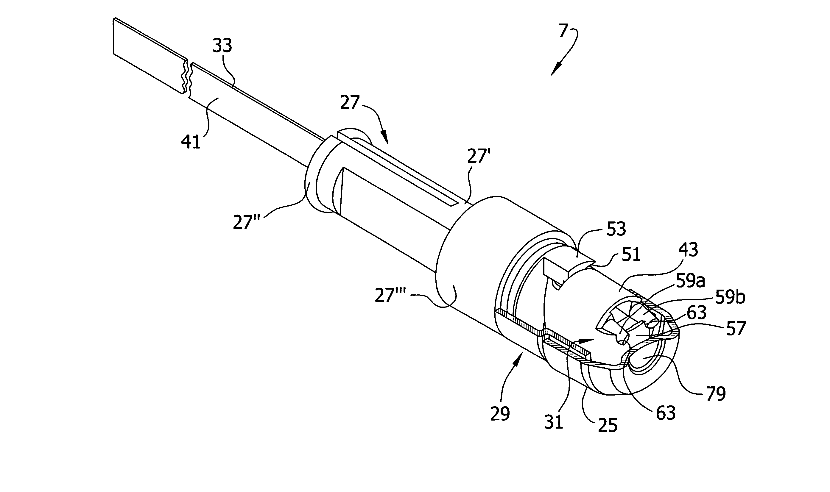
[0057] As with the probe shaft 19 of the first embodiment, the probe shaft element 127 received in the distal end of the tube 126 is assembled with the separator 129 and flex circuit 131. The tip 125 is pushed onto a subassembly of the probe shaft element 127, tube 126, separator 129 and flex circuit 131.

[0058] The cavity 146 on the interior of the forming section 145 strategically weakens an end surface 152 of the forming section. The tip 125 is sized and shaped so that it pushes the head 157 and the tip thermistor 135 downward, deforming the end surface 152 of the forming section 145 (FIG. 12). The material of the probe shaft element 127 is selected so that this deformation is resiliently resisted. Thus, the end surface 152 acts as a spring for forcing the portion of the head 157 opposite the tip thermistor 135 against a central region 179 of the tip 125, providing good thermal contact. Similarly, the cavity 146 weakens the curved surfaces 150 of the forming section 145. Thus when...

third embodiment

[0064]FIG. 16 illustrates a probe 207A having a modified probe shaft 219A, which like the probe shaft 219 shown in FIGS. 14 and 15 is constructed for snap connection of a separator to the probe shaft. Parts of the modified version of the probe shaft shown in FIG. 16 have the same reference numerals as for the third embodiment shown in FIGS. 14 and 15, but with the suffix “A”. The probe shaft 219A of FIG. 16 has substantially the same construction as the probe shaft 219 of FIGS. 14 and 15. A flange 254A and shoulder 262A formed in a forming section 245A of a probe shaft element 227A mechanically capture and retain a neck 234A of a separator 229A.

second embodiment

[0065] An outer wall 270A of the probe shaft element 227A angles inwardly from the shoulder 262A to the flange 254A. The angulation of the outer wall 270A has the same advantage as previously described for the curved surfaces 150 of the forming section 145 of the second embodiment shown in FIGS. 9-13. This construction helps to avoid having the separator 229A wipe off the epoxy from portions of the arms 243A opposite a separator thermistor 237A and resistor 239A when the separator is placed on a subassembly of the probe shaft element 227A and flex circuit 231A.

[0066] The modified version of FIG. 16 also differs from the embodiment of FIGS. 14 and 15 in that a support column 264A is constructed to provide a spring bias to the head 257A of the flex circuit 231A and tip thermistor 235A to press a portion of the head 257A of the substrate 233A opposite the tip thermistor against a central region 279A of a tip 225A of the probe. In that regard, the column 264A has an internal cavity 246A...


PUM


Abstract

An electronic thermometer has a probe that is used to receive heat from a subject such as a patient for measuring the temperature of the patient. The probe is particularly constructed for simplified, accurate and repeatable assembly of its various component parts.

Description

BACKGROUND OF THE INVENTION [0001] The invention pertains to the field of electronic thermometers and more particularly the field of fast response electronic thermometers employing a sensor probe. [0002] Electronic thermometers are widely used in the healthcare field for measuring a patient's body temperature. Typical electronic thermometers have the form of a probe with an elongated shaft. Electronic temperature sensors such as thermistors or other temperature sensitive elements are contained within the shaft portion. In one version, the probe includes a cup-shaped aluminum tip at its free end. A thermistor is placed in thermal contact with the aluminum tip inside the probe. When a free end portion is placed, for example, in a patient's mouth, the tip is heated up by the patient's body and the thermistor measures the temperature of the tip. Additional electronics connected to the electronic sensor components may be contained within a base unit connected by wire to the shaft portion...

Claims


Application Information

Patent Timeline
IPC IPC(8): A61B5/00G01K1/00
CPCG01K1/14G01K13/002G01K13/20G01K1/08G01K7/00
Inventor SISK, RICKY A.GIERER, JOSEPH T.HARR, JAMESKIMSEY, SCOTT
Owner COVIDIEN AG
Why Eureka
Try Eureka