
Multiangle cutting saw

a multi-angle cutting and sawing technology, applied in the field of saws, can solve the problems of inability to adjust, inability to transport easily, and large sawing siz

Inactive Publication Date: 2007-05-10
JPJ INVESTMENT HLDG
View PDF61 Cites 9 Cited by
  • Summary
  • Abstract
  • Description
  • Claims
  • Application Information

AI Technical Summary

Benefits of technology

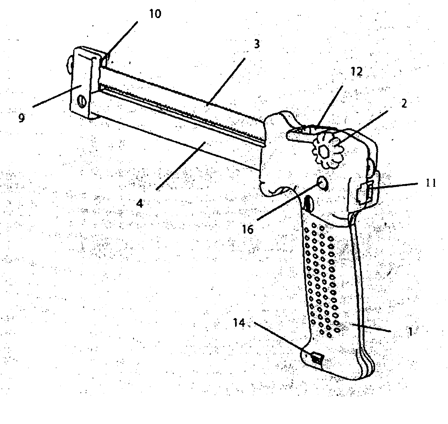
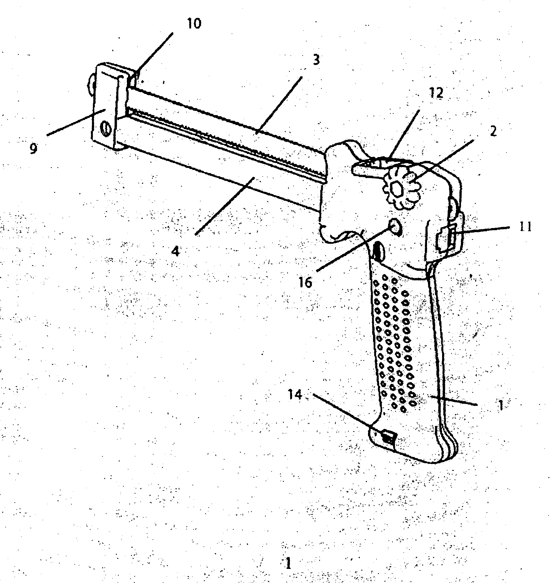
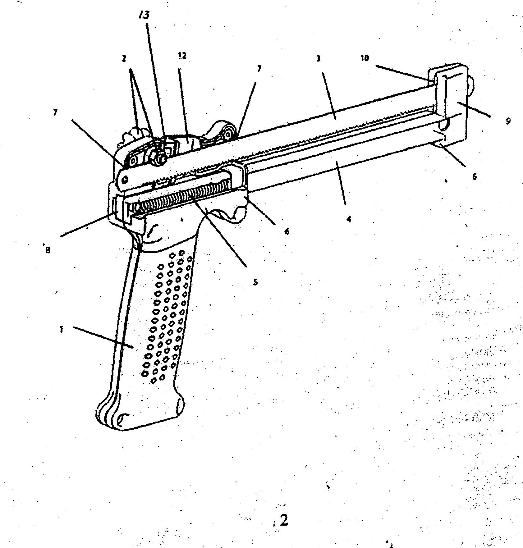
[0013] A multi-angle cutting saw that can protect saw teeth from damage, perform multi-angle cutting, and is easy to transport, is provided. The saw includes a handle, a locking bolt, a saw blade, a guide block, and a return mechanism. The saw blade can be installed in the horizontal saw blade hole of the handle through the locking bolt. The guide block, which can be parallel to the saw blade and can rotate along with the saw blade and can penetrate through the handle, can be installed in the horizontal guide hole on the bottom surface of the horizontal saw blade hole in the handle. The saw blade can pass through the saw slot at the upper end of a support frame. The support frame, which can move along the saw blade together with the guide block, can be installed at the end of the guide block. The return mechanism, which is installed inside the upper end of the handle and can drive the guide block to move, can be connected to the spring clip at the other end of the guide block. A position limiting device, which can stop movement of the guide block, can be installed at the lower end of the support frame. A hole can be formed outside the horizontal guide hole at the upper end of the handle. A horizontal stop piece can be installed outside the horizontal guide hole.

Problems solved by technology

This saw, however, suffers from a working angle that is fixed and cannot be adjusted; and the saw is too large and cannot be transported easily.

Method used


Image

  • Multiangle cutting saw
  • Multiangle cutting saw
  • Multiangle cutting saw

Examples


Embodiment Construction

[0014] A detailed description will now be provided. Each of the appended claims defines a separate saw, which for infringement purposes is recognized as including equivalents to the various elements or limitations specified in the claims. Depending on the context, all references below to the “saw” may in some cases refer to certain specific embodiments only. In other cases it will be recognized that references to the “saw” will refer to subject matter recited in one or more, but not necessarily all, of the claims. Each of the saws will now be described in greater detail below, including specific embodiments, versions and examples, but the saws are not limited to these embodiments, versions or examples, which are included to enable a person having ordinary skill in the art to make and use the saws, when the information in this patent is combined with available information and technology.

[0015] In one or more embodiments, a saw is provided that has a small volume and can perform mult...


PUM

PropertyMeasurementUnit
shapesaaaaaaaaaa
relative movementaaaaaaaaaa
volumeaaaaaaaaaa

Abstract

A multi-angle cutting saw that can protect saw teeth from damage, perform multi-angle cutting, and is easy to transport, is provided. The saw includes a handle, a locking bolt, a saw blade, a guide block, and a return mechanism. The saw blade can be installed in the horizontal saw blade hole of the handle through the locking bolt. The guide block, which can be parallel to the saw blade and can rotate along with the saw blade and can penetrate through the handle, can be installed in the horizontal guide hole on the bottom surface of the horizontal saw blade hole in the handle. The saw blade can pass through the saw slot at the upper end of a support frame. The support frame, which can move along the saw blade together with the guide block, can be installed at the end of the guide block. The return mechanism, which is installed inside the upper end of the handle and can drive the guide block to move, can be connected to the spring clip at the other end of the guide block. A position limiting device, which can stop movement of the guide block, can be installed at the lower end of the support frame. A hole can be formed outside the horizontal guide hole at the upper end of the handle. A horizontal stop piece can be installed outside the horizontal guide hole.

Description

CROSS REFERENCE TO RELATED APPLICATION [0001] This application claims the benefit under 35 USC §119 of Chinese Patent Application having Application Serial No. 200510030343.3 filed on Oct. 10, 2005, which is incorporated by reference herein. BACKGROUND OF THE INVENTION [0002] 1. Field of the Invention [0003] Embodiments of the present invention generally relate to a saw. More particularly, embodiments of the present invention relate to a type of saw that can perform multi-angle cuts with respect to various types of materials in various shapes. [0004] 2. Description of the Related Art [0005] Saws are popular tools used in daily life. UK Patent Application No. 2353756, c1.B23D49 / 10, 07.03.2001 / filed in 2001 describes a saw that includes a handle, saw blade, guide block, and return mechanism. The saw blade is sandwiched between the handle and the guide block. The return mechanism can control the relative movement between the handle and the guide block. This saw, however, suffers from a...

Claims


Application Information

Patent Timeline
Patent Type & Authority Applications(United States)
IPC IPC(8): B27B21/00
CPCB23D49/10B27B21/04
Inventor WEN PETER (HAO)
Owner JPJ INVESTMENT HLDG
Learn More