Flashing boots for roof penetrations

Active Publication Date: 2007-05-10
HEARTLAND METALS
View PDF33 Cites 52 Cited by
  • Summary
  • Abstract
  • Description
  • Claims
  • Application Information

AI Technical Summary

Benefits of technology

[0014] The present invention overcomes the aforementioned limitations and disadvantages present in the art by providing improved flashing for use with metal and non-metal roof systems. In a first embodiment, a lead flashing assembly is provided comprising: a generally planar lead base defining an aperture; a generally cylindrical structure attached to the base in surrounding relation with the aperture and projecting upward therefrom; and an adhesive sealing membrane attached to the bottom of the base for connecting the flashing to a roof The adhesive sealing membrane is not only effective in securing the flashing to the underlying roof, but further functions as a gasket separating the lead flashing base from a metal roof This first embodiment is particularly well adapted for use on metal roofs.

Problems solved by technology

While this configuration is generally suitable for non-metal roofs, the use of lead flashing with metal roof decks has been avoided due largely to increased corrosion resulting from possible electrolytic reactions between dissimilar metals, as well as difficulty in forming a watertight seal between a metal roof deck and a lead flashing base.

Method used


Image

  • Flashing boots for roof penetrations
  • Flashing boots for roof penetrations
  • Flashing boots for roof penetrations

Examples


Embodiment Construction

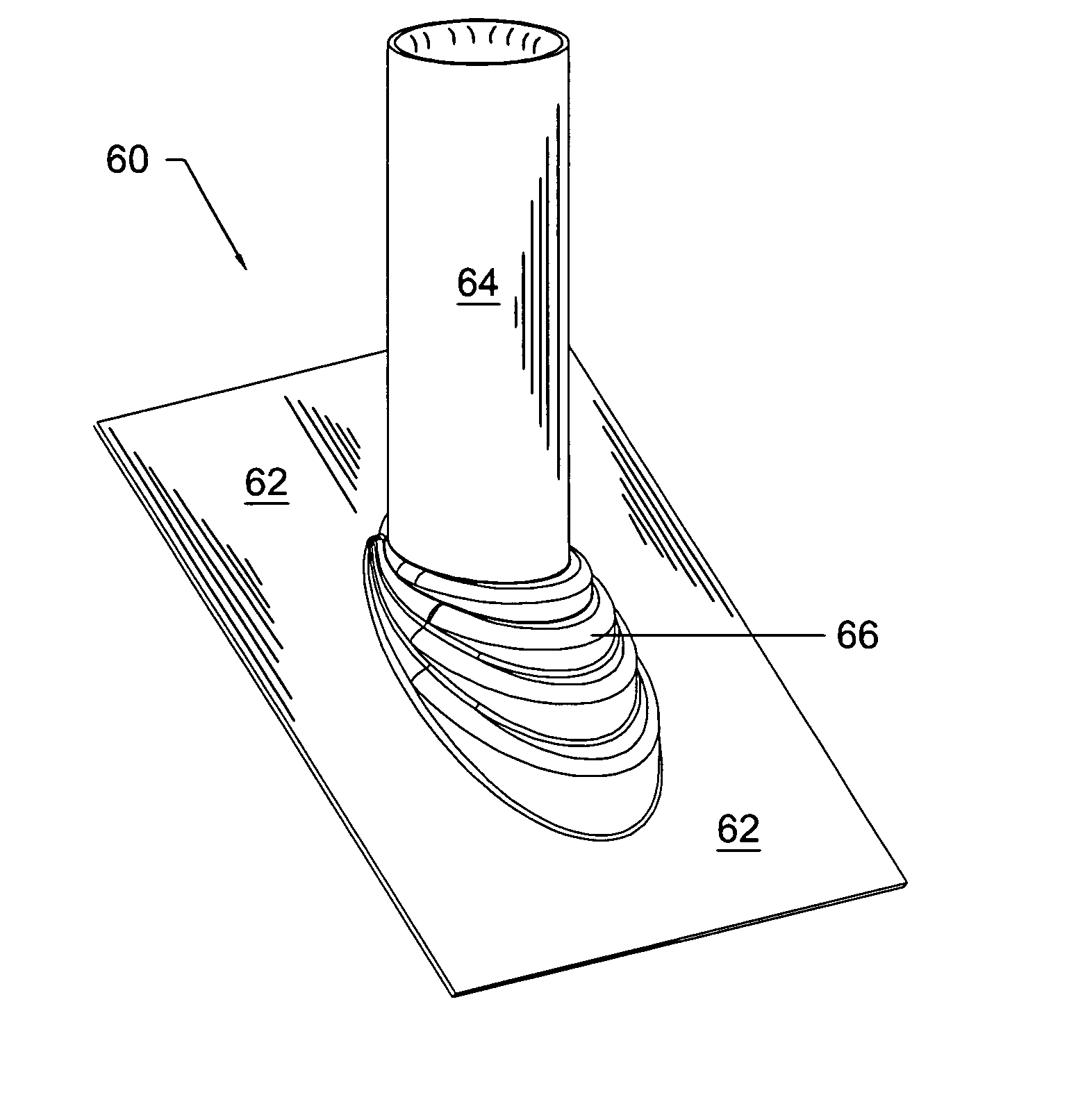
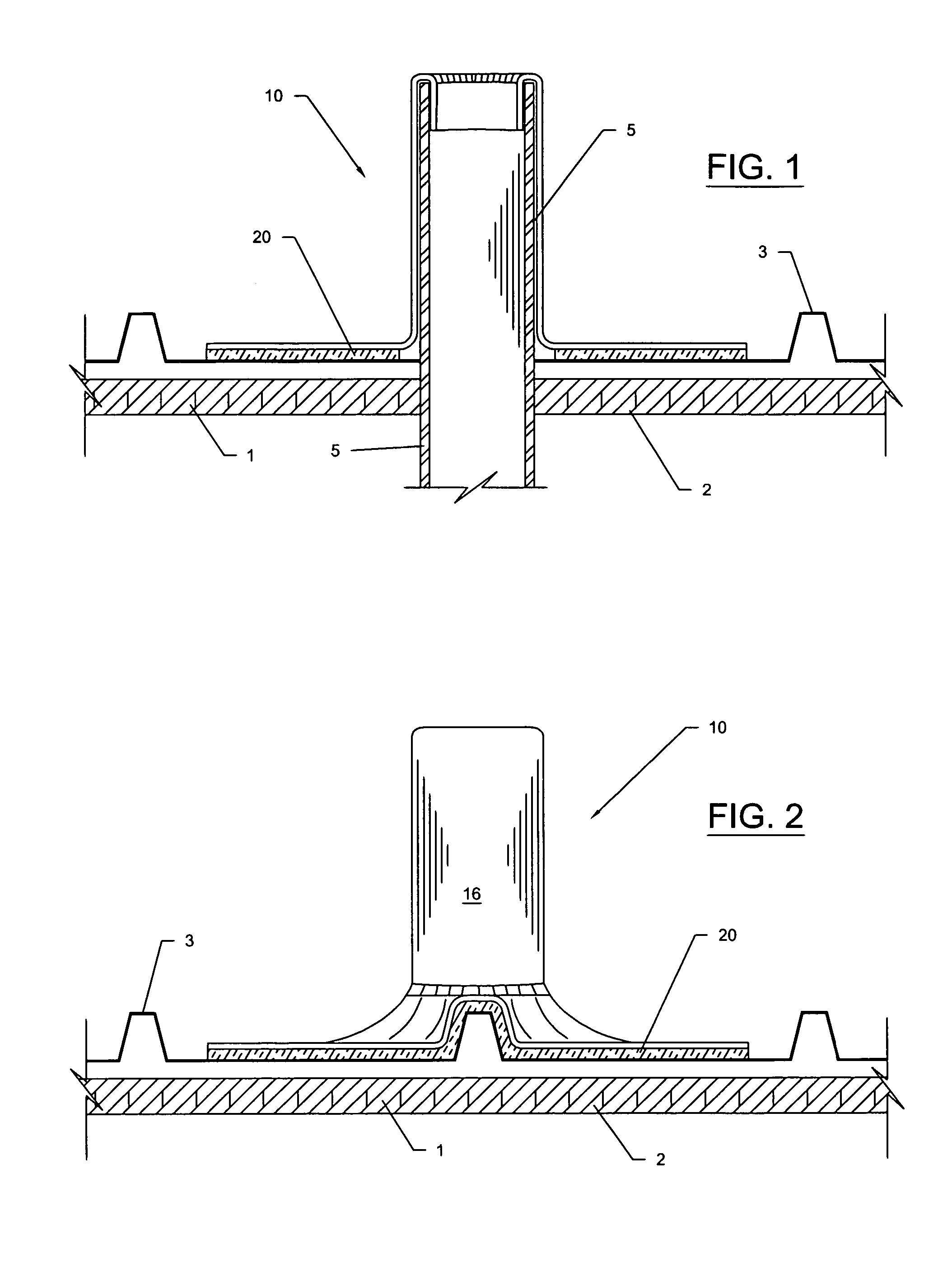
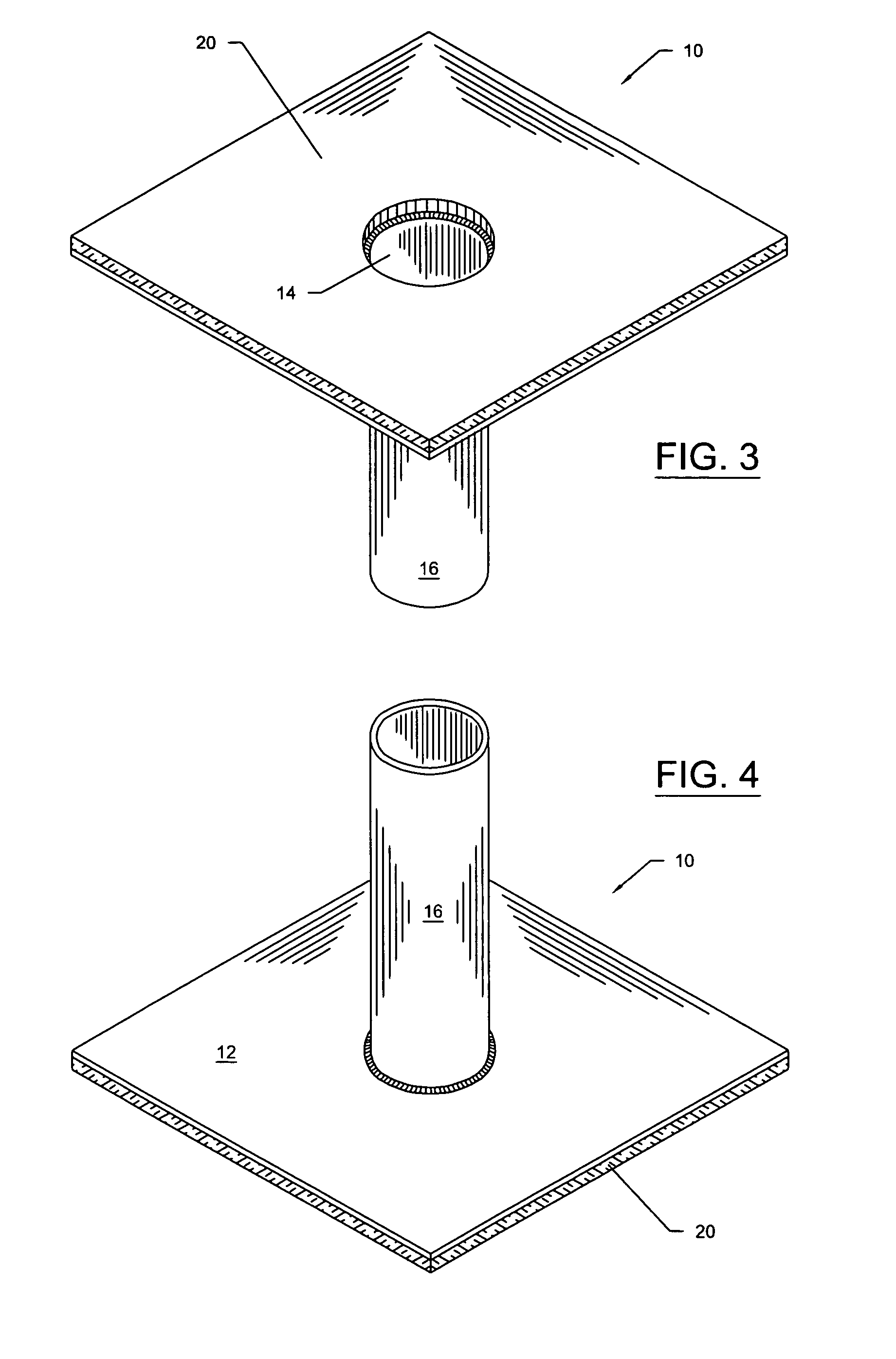
[0052] With reference now to the drawings, FIGS. 1-30 depict roof flashing systems in accordance with the present invention.

[0053]FIGS. 1-7 disclose lead roof flashing systems that are particularly suitable for use with penetrations in metal roofs. Turning first to FIGS. 1-4, there is depicted a first embodiment roof flashing assembly, generally referenced as 10. FIGS. 1 and 2 depict flashing assembly 10 installed on a roof, generally referenced as 1, including a roof deck 2 and a metal roof surface 3, in relation with a roof penetration, referenced as 5. As best seen in FIGS. 3 and 4, flashing assembly 10 includes a lead flashing structure having a generally planar lead base 12 defining an aperture 14, and a generally cylindrical stack 16 attached to the base in surrounding relation with an aperture 14 and projecting upward from base 12. Base 12 further includes a bottom surface adapted with an adhesive sealing membrane 20 adhesively attached to the bottom of base 12 for connectin...


PUM


Abstract

Improved flashing systems are disclosed for use with metal and non-metal roof systems. A lead flashing apparatus is provided comprising a generally planar lead base defining an aperture, a generally cylindrical structure attached to the base in surrounding relation with the aperture and projecting upward therefrom, and an adhesive sealing membrane attached to the bottom of the base for connecting the flashing to a roof The adhesive sealing membrane is not only effective in securing the flashing to the underlying roof, but further functions as a gasket separating the lead flashing base from a metal roof In a second embodiment, lead flashing having a generally planar base and upwardly projecting stack is adapted with a non-metallic coating. In a third embodiment, a flashing structure is fabricated from plastic, and preferably includes a sloped base with a tapered stack and is suitable for use on virtually any roof system. In any of the various embodiments disclosed herein, the base may be angled relative to the stack such that the flashing structure is suitable for use on pitched roofs. In a fourth embodiment, flashing is formed of a resilient material having a stepped accordion base that allows for the stack to be angularly adjusted relative to the base. In a fifth embodiment, the stepped accordion base is configured in a partial circumferential configuration on the downward portion of a sloped base, which partial circumferential configuration allows for the stack to be angularly adjusted relative to the base. In a sixth embodiment, a flashing system is provided with mating top and bottom flashings, each of which includes a stepped accordion base. In a seventh embodiment, a one-size-fits-all flashing system is disclosed wherein a flashing base is provided with an elongated triangular stack, for installation on a variety of pitched roofs.

Description

CROSS REFERENCE TO RELATED APPLICATIONS [0001] This application claims the benefit of provisional U.S. Patent Application Ser. No. 60 / 725,753, filed on Oct. 12, 2005.STATEMENT REGARDING FEDERALLY SPONSORED RESEARCH OR DEVELOPMENT [0002] N / A COPYRIGHT NOTICE [0003] A portion of the disclosure of this patent document contains material that is subject to copyright protection. The copyright owner has no objection to the facsimile reproduction by anyone of the patent document or patent disclosure as it appears in the Patent and Trademark Office patent file or records, but otherwise reserves all copyrights rights whatsoever. BACKGROUND OF THE INVENTION [0004] 1. Field of the Invention [0005] The present invention relates to flashing and sealing systems for roof penetrations. [0006] 2. Description of Related Art [0007] Flashing is commonly used on roofs at locations where the watertight integrity of the roof is compromised by a penetration, such as a pipe or other penetrating structure. Fl...

Claims


Application Information

Patent Timeline
Patent Type & Authority Applications(United States)
IPC IPC(8): E04B7/00
CPCE04D13/1407E04D13/1476
Inventor HOY, MIKEEDGEMON, JACKHOY, JOHN
Owner HEARTLAND METALS
Why Eureka
Try Eureka