Accumulator

a technology of accumulator and accumulator plate, which is applied in the direction of accumulator installation, actuator accumulator, pipe element, etc., can solve the problems of increasing the b/c curve, increasing the b/c thinning the 1/b> of the backing metal portion, so as to reduce the number of parts, reduce the working steps, and reduce the volume adjusting spacer

Inactive Publication Date: 2007-05-10
NOK CORP
View PDF7 Cites 24 Cited by
  • Summary
  • Abstract
  • Description
  • Claims
  • Application Information

AI Technical Summary

Benefits of technology

[0013] In the accumulator in accordance with the first aspect of the present invention having the structure mentioned above, since the cross sectional inner outline of the peripheral edge portion of the gas end cover is the oval shape which is concave to the pressure sealed chamber side, and the dead space is not formed, it is possible to make a capacity of the volume adjusting spacer small, and it is possible to make entire weight light as well as it is possible to make the entire of the accumulator small in an axial direction.
[0014] Further, since the cross sectional inner outline of the peripheral edge portion is the oval shape which is concave to the pressure sealed chamber side, the thickness of the end portion is thick, and since it is not necessary to employ the shape in which the end portion of the peripheral edge portion is curved to the inner diameter side for forming the fixing portion to fix the metallic bellows, it is easy to work the gas end cover, and the working steps can be reduced.
[0015] Further, since the cross sectional inner outline of the peripheral edge portion is the oval shape which is concave to the pressure sealed chamber side, the thickness of the end portion is thick, it is possible to make the backing metal portion thick even if the step concave portion bonding to the end surface of the shell is formed, and it is possible to sufficiently secure the welding penetration depth at a time of welding to the shell.
[0016] Further, in the invention in accordance with the second aspect, since the hexagon nut shape corresponding to the position to which a tool such as a spanner or the like is applied for screwing the accumulator to a piping is integrally formed with the gas end cover, it is possible to reduce the number of parts, it is possible to omit a step of fixing a hexagon nut, and it is possible to simplify an assembling step of the housing.

Problems solved by technology

Further, since the shape in which the end portion of the peripheral edge portion 105 is largely curved to the inner diameter side is employed for securing the fixing portion 108 as mentioned above, there is a problem that working steps for making the gas end cover 104 in the curved shape is increased.
However, if the peripheral edge portion is formed in the curved shape, there occurs a problem that a thickness W1 of the backing metal portion becomes thin and there is a limit for securing a depth of weld penetration.
In this case, Japanese Unexamined Patent Publication No. 2002-122101 (Patent Document 1) proposes a structure in which a shape of a cross sectional center portion is formed in a convex shape to the pressure sealed chamber side and in a concave shape in the peripheral edge portion in order to secure strength in a state in which the thickness of the gas end cover is thin, however, since the peripheral edge portion is formed in the concave shape to the pressure sealed chamber side, the dead space exists, so that the structure cannot be effective for making the volume adjusting spacer small and making the working steps of the gas end cover easy.

Method used


Image

  • Accumulator
  • Accumulator
  • Accumulator

Examples


Embodiment Construction

[0037] Next, a description will be given of an embodiment in accordance with the present invention with reference to the companying drawings. In this case, the scope of the invention is not limited to the contents described in the mode for carrying out the invention unless any specific limited description is given.

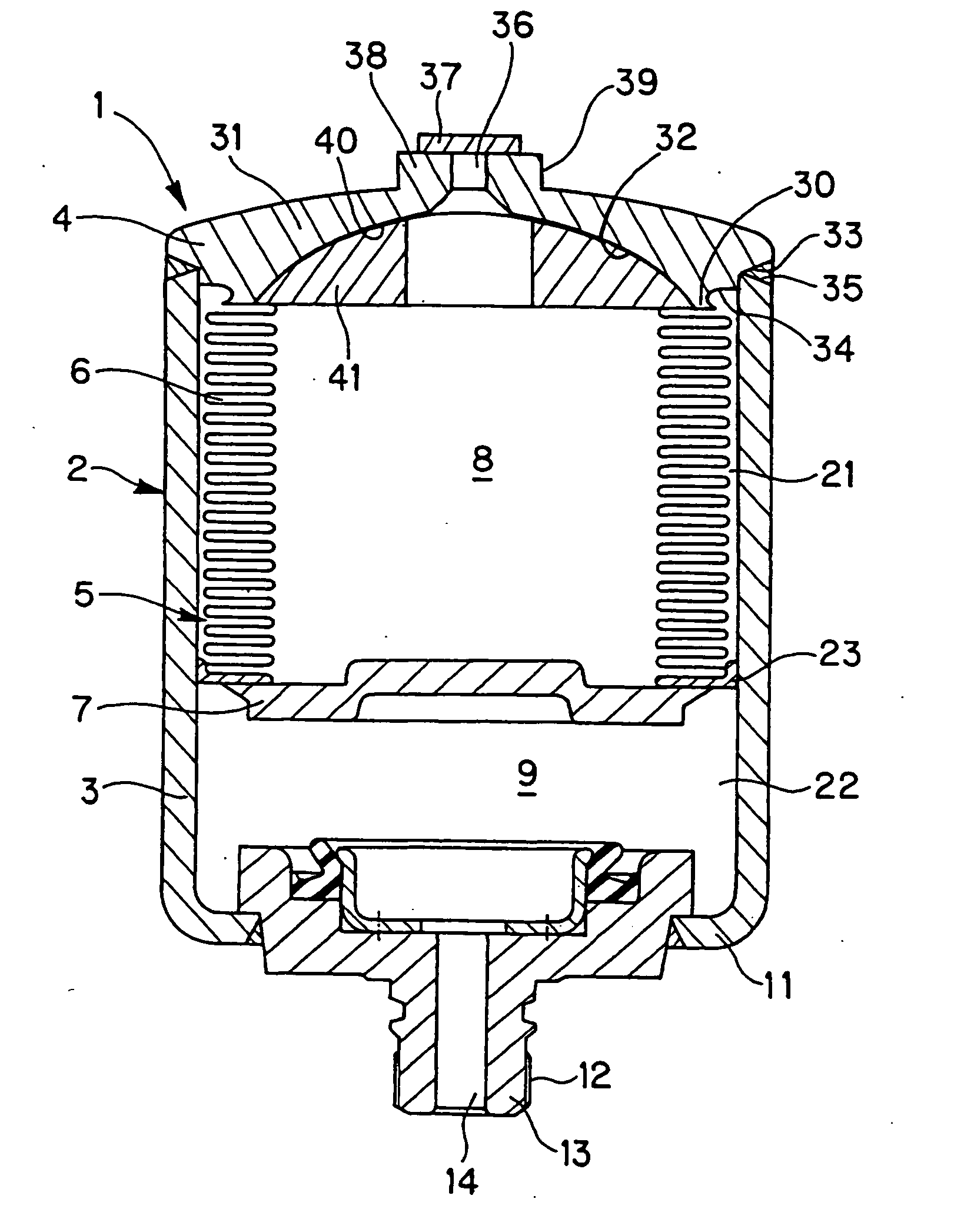
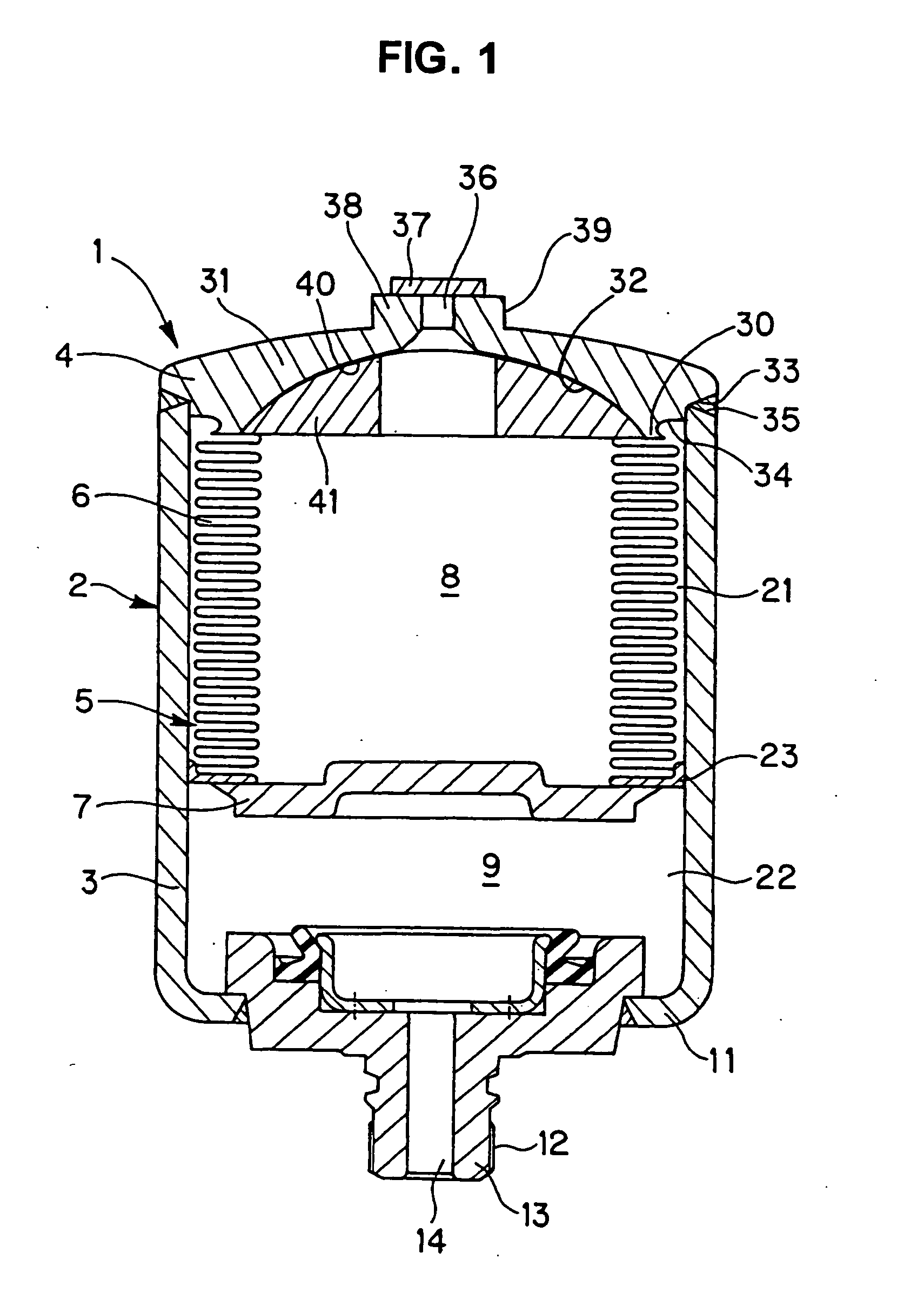
[0038] An accumulator 1 in accordance with the embodiment corresponds to a metallic bellows type accumulator, and is structured as follows.

[0039] First, as shown in FIG. 1, a housing 2 is provided in such a manner that a gas end cover 4 is fixed to an open end portion of a bottomed tubular shell 3, and an operation member 5 provided with a metallic bellows 6 and a bellows cap 7 is accommodated in an inner portion of the housing 2. The metallic bellows 6 is structured such that one end portion is fixed to the gas end cover 4, and the other end portion is fixed to the bellows cap 7. Accordingly, an inner portion of the housing is sectioned into a pressure sealed chamber 8 ...


PUM


Abstract

An accumulator in which a pressure sealed chamber and a pressure flow-in chamber are formed by an operation member including a metallic bellows provided within a housing constituted by a gas end cover and a bottomed tubular shell, wherein a cross sectional inner outline of a peripheral edge portion of the gas end cover is an oval shape which is concave to the pressure sealed chamber side, and a dead space is not formed, so that a capacity of a volume adjusting spacer is reduced by eliminating a dead space, a working step is reduced by simplifying a shape of the gas end cover, and a margin of welding penetration depth is increased by thickening of a backing metal portion.

Description

[0001] This is a nationalization of PCT Application of International Publication No. WO 2005 / 052381 published on Jun. 9, 2005. TECHNICAL FIELD [0002] The present invention relates to an accumulator used as a pressure accumulating apparatus, a pulsation damping apparatus or the like. The accumulator in accordance with the present invention is used in a hydraulic apparatus of a vehicular brake system and various industrial fluid pressure systems. BACKGROUND ART [0003] For example, in the hydraulic apparatus of the vehicular brake system, for the purpose of pressure accumulation or pulsation damping, there is employed an accumulator in which a pressure sealed chamber and a pressure flow-in chamber are formed by an operation member including a flexible metallic bellows. The accumulator is structured such as to damp and absorb a vibration by balancing a pressure in the pressure sealed chamber determined by the expansion and contraction of the metallic bellows and a pressure in the pressu...

Claims


Application Information

Patent Timeline
Patent Type & Authority Applications(United States)
IPC IPC(8): F16L55/04F15B1/08F15B1/10
CPCF15B1/103F15B1/106F15B2201/205F15B2201/3153F15B2201/41F15B2201/415
Inventor YOSHIHARA, HISAOSASAKI, KENJI
Owner NOK CORP
Why Eureka
Try Eureka