Coal-fired power station

Inactive Publication Date: 2006-02-07
STEAG ENERGY SERVICES
View PDF10 Cites 59 Cited by
  • Summary
  • Abstract
  • Description
  • Claims
  • Application Information

AI Technical Summary

Benefits of technology

[0007]To realize this object, the inventive coal-fired power station is characterized by providing a coarse ash separator disposed upstream of the catalytic converter in a section of the flue gas channel, wherein the flue gas channel inclu

Problems solved by technology

This leads to the originally dry, pulverous ash particles sticking together or even sintering together.
Coarse ash particles result that although they enter the catalyzer channels, they can become caught there and together build up to form obstructi

Method used


Image

  • Coal-fired power station
  • Coal-fired power station
  • Coal-fired power station

Examples


Example

DESCRIPTION OF THE DRAWINGS

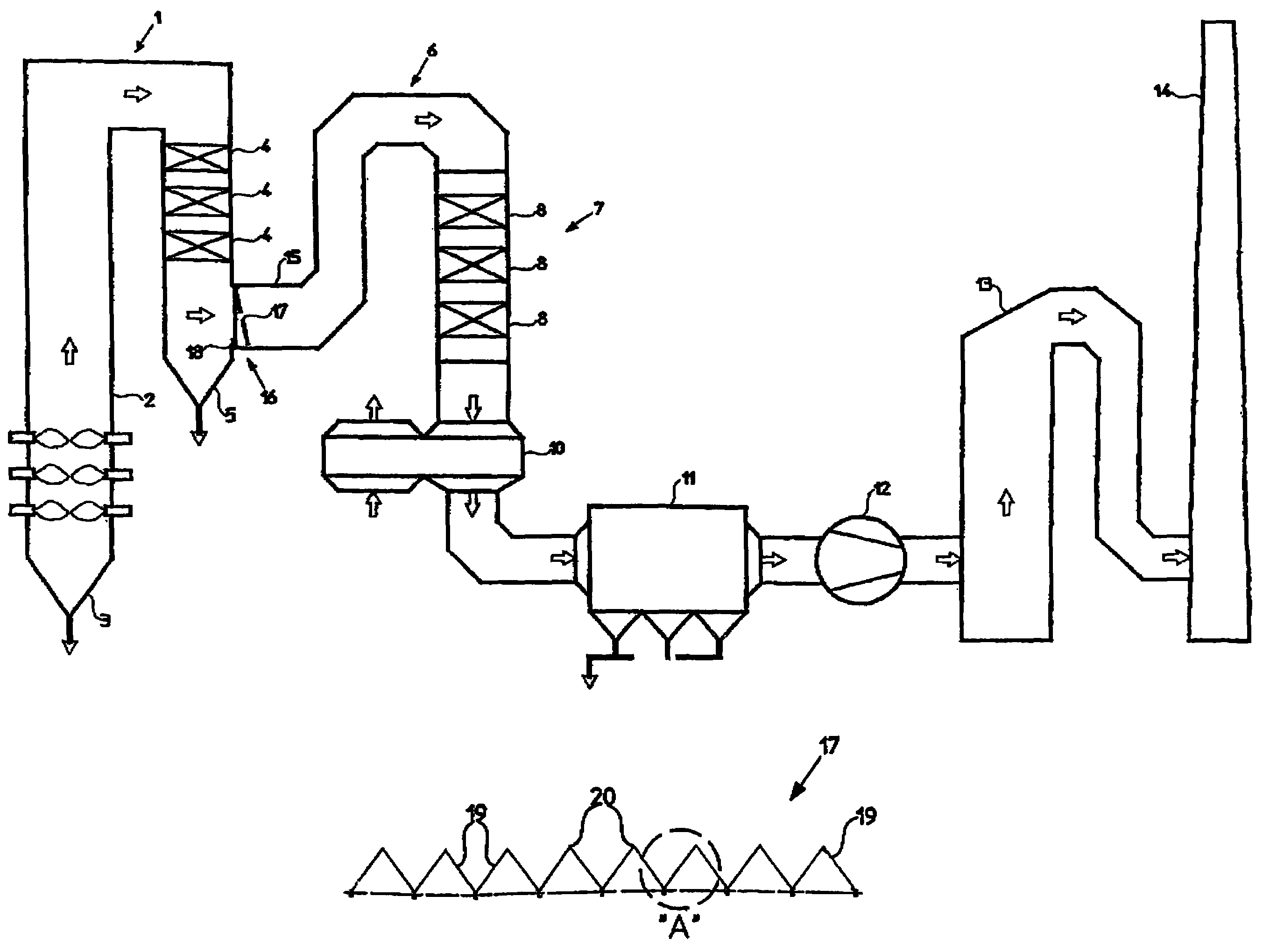
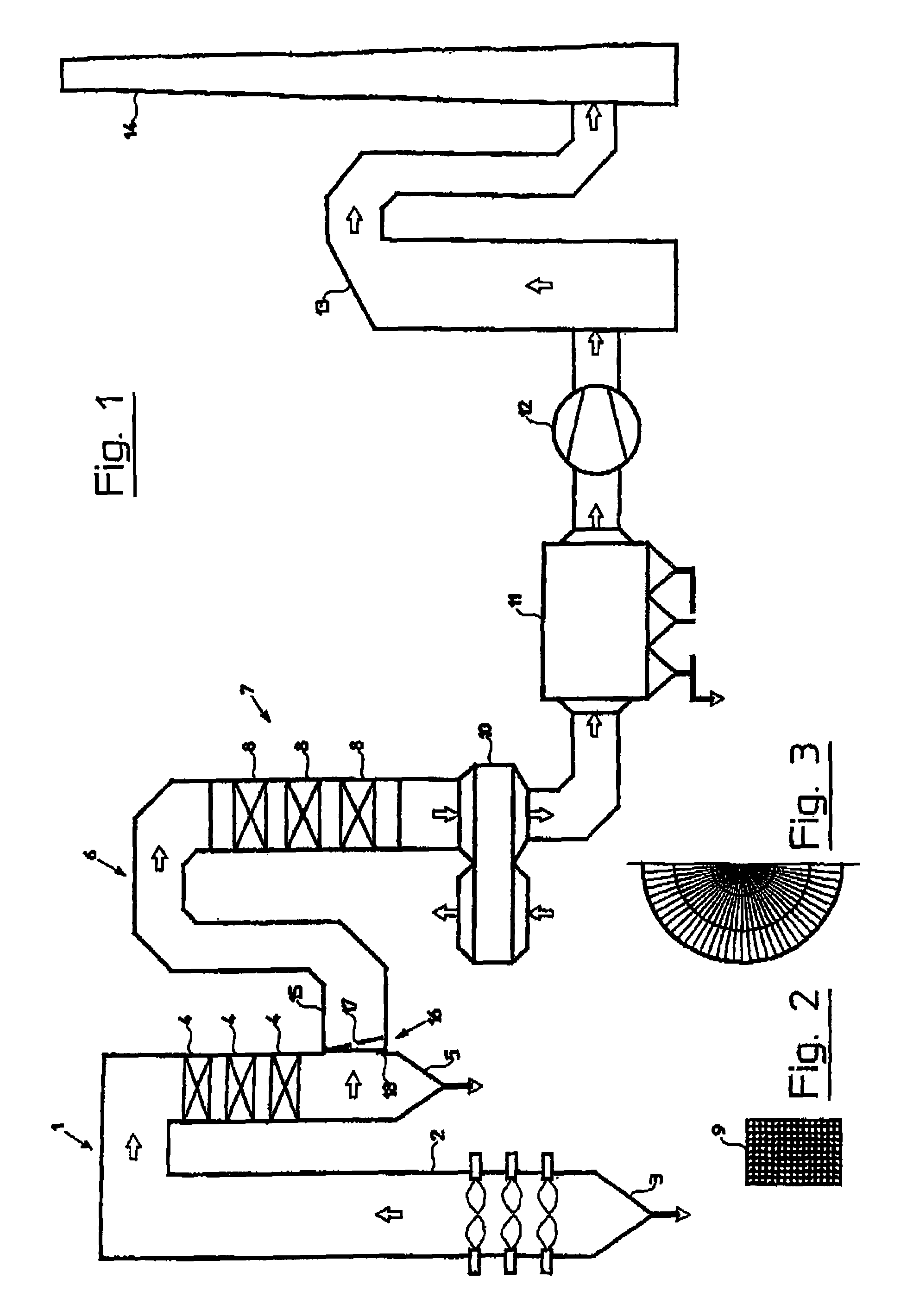
[0028]The coal-fired power plant or station of FIG. 1 is provided with a boiler 1 having a combustion chamber or firebox 2 for a dry firing, whereby an ash funnel 3 adjoins the combustion chamber 2. The boiler 1 furthermore includes heat exchangers 4, with a further ash funnel 5 adjoining the housings of the heat exchangers. The boiler 1 is connected via a flue gas channel 6 with a catalyzer or catalytic converter 7 for reducing the NOx level. The latter has a plurality of catalyzer stages 8 that are respectively composed of modules 9 (see FIG. 2). The dimensions of the channels formed by the modules 9 are 7.1 mm×7.1 mm×1000 mm.

[0029]Adjoining the catalytic converter 7 is an air pre-heater 10 that operates regeneratively and the units or baffles of which can be seen from the half illustration of FIG. 3. Following this are an electrostatic filter 11, an induced-draft blower 10 and a REA (flue gas desulfurization unit) scrubber 13, from which the cleaned flu...


PUM

PropertyMeasurementUnit
Forceaaaaaaaaaa
Angleaaaaaaaaaa

Abstract

A coal-fired power station is provided and has a boiler that is heatable by dry firing, a catalytic converter for reducing an NOx level, a flue gas channel that adjoins the boiler and leads to the catalytic converter, and a coarse ash separator disposed upstream of the catalytic converter in a section of the flue gas channel, which includes a sieve that extends essentially over an entire cross-sectional area thereof. The sieve is adapted to be deflected out of a position of rest by a flue gas stream and against the effect of a restoring force, and/or the sieve forms folds that are directed in an upstream direction relative to a flue gas stream and extend essentially parallel to one another.

Description

[0001]The specification incorporates by reference the disclosure of German priority document 102 27 639.0 filed Jun. 20, 2002 and PCT / EP2002 / 014633 filed Dec. 20, 2002.[0002]The present invention is, of course, in no way restricted to the specific disclosure of the specification and drawings, but also encompasses any modifications within the scope of the appended claims.BACKGROUND OF THE INVENTION[0003]The invention relates to a coal-fired power plant or station having a boiler that can be heated by a dry firing, and with a flue gas channel that adjoins the boiler and that leads to a catalytic converter for reducing the NOx level.[0004]During dry firings, the ash is produced as dry dust that is partially withdrawn at the bottom out of the combustion chamber, but also is partially carried along by the flue gas stream. The catalytic converter for reducing the NOx level comprises packings of narrow channels, and the carried-along dust has the tendency to accumulate on the catalyzer sur...

Claims


Application Information

Patent Timeline
IPC IPC(8): F23J3/00B01D46/10B01D53/86F23J15/02
CPCB01D46/0053B01D46/0075B01D46/10B01D53/8631F23J15/02B01D46/125F23J2217/10B01D2267/40B01D46/121B01D46/76
Inventor GROMMES, KLAUSSCHULTHOFF, WOLFGANG
Owner STEAG ENERGY SERVICES
Why Eureka
Try Eureka