Camber angle controlling device

a technology of controlling device and camera angle, which is applied in the direction of vehicle position/course/altitude control, process and machine control, instruments, etc., can solve the problem that the gripping force of the tire cannot be brought out sufficiently, and achieve the effect of high gripping force, low rolling resistance, and high gripping property

Inactive Publication Date: 2010-08-26
EQUOS RES
View PDF7 Cites 64 Cited by
  • Summary
  • Abstract
  • Description
  • Claims
  • Application Information

AI Technical Summary

Benefits of technology

[0014]With the camber angle controlling device according to claim 1, because the camber angle adjusting means controls the camber angle applying device, a camber angle in the negative direction or positive direction is applied to the wheel, and thereby the camber angle of the wheel is adjusted to the predetermined value. Consequently, it is possible to selectively use the characteristics (high gripping property) of a high gripping force and the characteristics (low rolling resistance) of a small rolling resistance, as a performance of the wheel.
[0015]Therefore, there is an effect that the energy consumption of the vehicle can be reduced by using the low rolling resistance of the wheel while ensuring the running performance (such as a turning performance, an accelerating performance or a braking performance) of the vehicle by using the high gripping property of the wheel.
[0016]In addition, according to the present invention, the camber angle controlling device includes the traveling information acquiring means that acquires the traveling information of the vehicle, and the camber angle adjusting means controls the camber angle applying device based on the traveling information acquired by the traveling information acquiring means so as to make the rolling resistance of the wheel smaller. Therefore, there is an effect that the energy loss generated in the wheel during running can be made smaller, thereby enabling to aim at a further reduction in the energy consumption of the vehicle.
[0017]Here, if the wheel is structured by arranging, in the direction of the width thereof, treads of two or more types, for example, of a first tread configured to have the characteristics (high gripping property) of a high gripping force and a second tread configured to have the characteristics (low rolling resistance) of a small rolling resistance, the ratio of ground contact area between the first tread and the second tread can be controlled by adjusting the camber angle of the wheel. Thus, it is possible to selectively use the high gripping property and the low rolling resistance so as to reduce the energy consumption of the vehicle while ensuring the running performance thereof.
[0018]In addition, if the wheel is composed of a tread of one type, it is also possible to selectively use the characteristics (high gripping property) of a high gripping force and the characteristics (low rolling resistance) of a small rolling resistance so as to reduce the energy consumption of the vehicle while ensuring the running performance thereof, by adjusting the camber angle of the wheel to control the amount of deformation of the wheel.
[0019]In addition to the effect achieved by the camber angle controlling device according to claim 1, the camber angle controlling device according to claim 2 further includes the required coefficient of friction calculating means that calculates the required coefficient of friction, and the camber angle adjusting means adjusts the camber angle of the wheel based on the required coefficient of friction calculated by the required coefficient of friction calculating means. Therefore, slip of the wheel can be suppressed. As a result, there is an effect that the wasteful consumption of energy associated with the slip of the wheel can be suppressed, thereby enabling to aim at a further reduction in the energy consumption of the vehicle. In addition, there is an effect that the running performance of the vehicle can be ensured in a reliable manner. Note that the required coefficient of friction refers to a coefficient of friction that is required so that the wheel does not slip.

Problems solved by technology

The reason for this is that, if, for example, the camber angle is set to zero degrees, the wheel lifts from the road surface because a vehicle body rolls during turning, and thus the gripping force of the tire cannot be brought out sufficiently.

Method used


Image

  • Camber angle controlling device
  • Camber angle controlling device
  • Camber angle controlling device

Examples


first embodiment

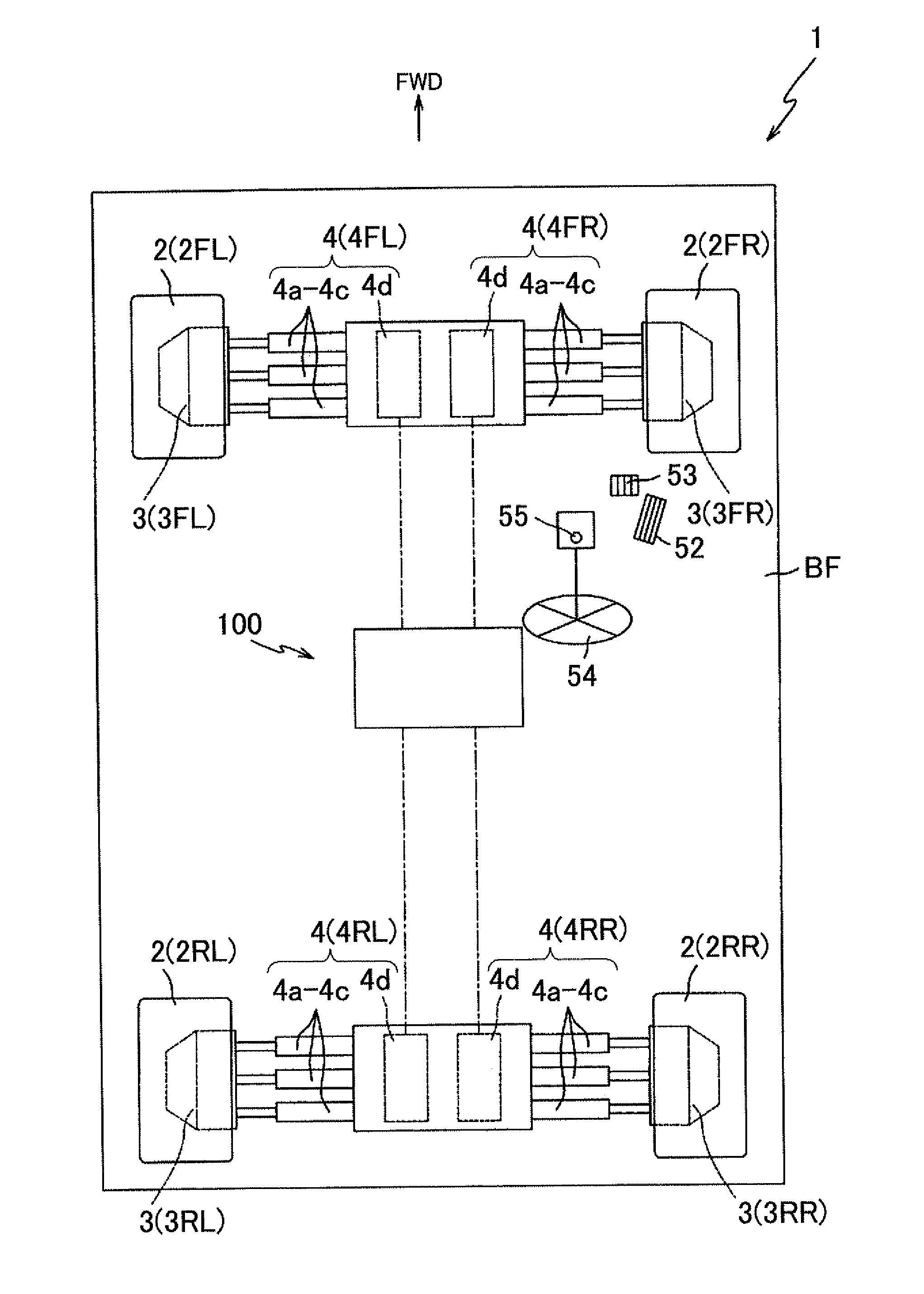
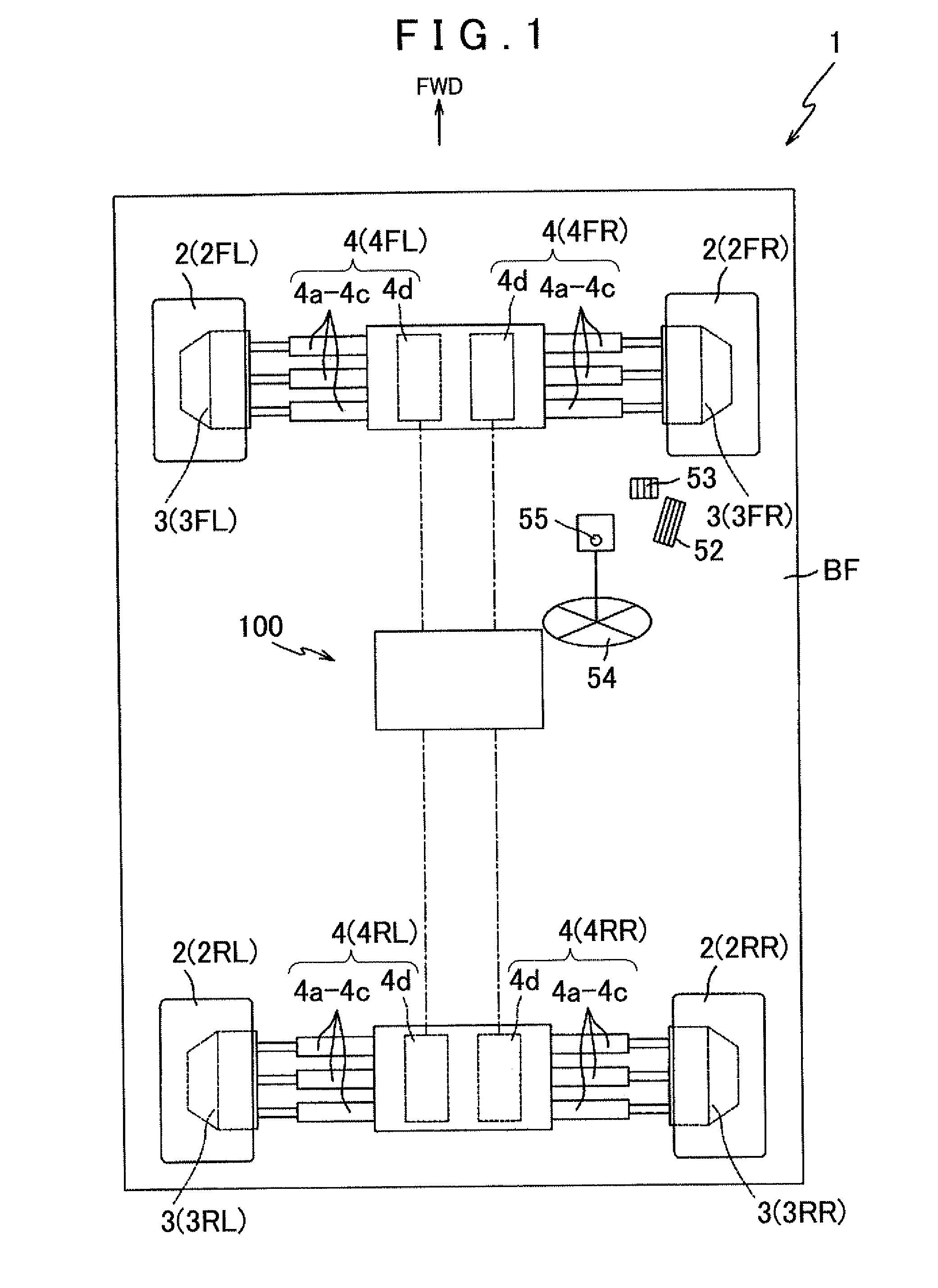
[0126]Preferred embodiments of the present invention will be described below with reference to the accompanying drawings. FIG. 1 is a schematic diagram schematically showing a top view of a vehicle 1 equipped with a vehicular control device 100 according to the present invention. Note that an arrow FWD in FIG. 1 indicates the forward direction of the vehicle 1.

[0127]First of all, an outline structure of the vehicle 1 will be described. As shown in FIG. 1, the vehicle 1 is mainly provided with a vehicle body frame BF, a plurality of (four in the present embodiment) wheels 2 supported by the vehicle body frame BF, a wheel driving mechanism 3 that rotationally drives each of the wheels 2, and a camber angle applying device 4 that drives each of the wheels 2 for steering motion and camber angle adjustment thereof. The vehicle 1 is structured such that the vehicular control device 100 controls the operation of the camber angle applying device 4 to adjust the camber angles of the wheels 2...

second embodiment

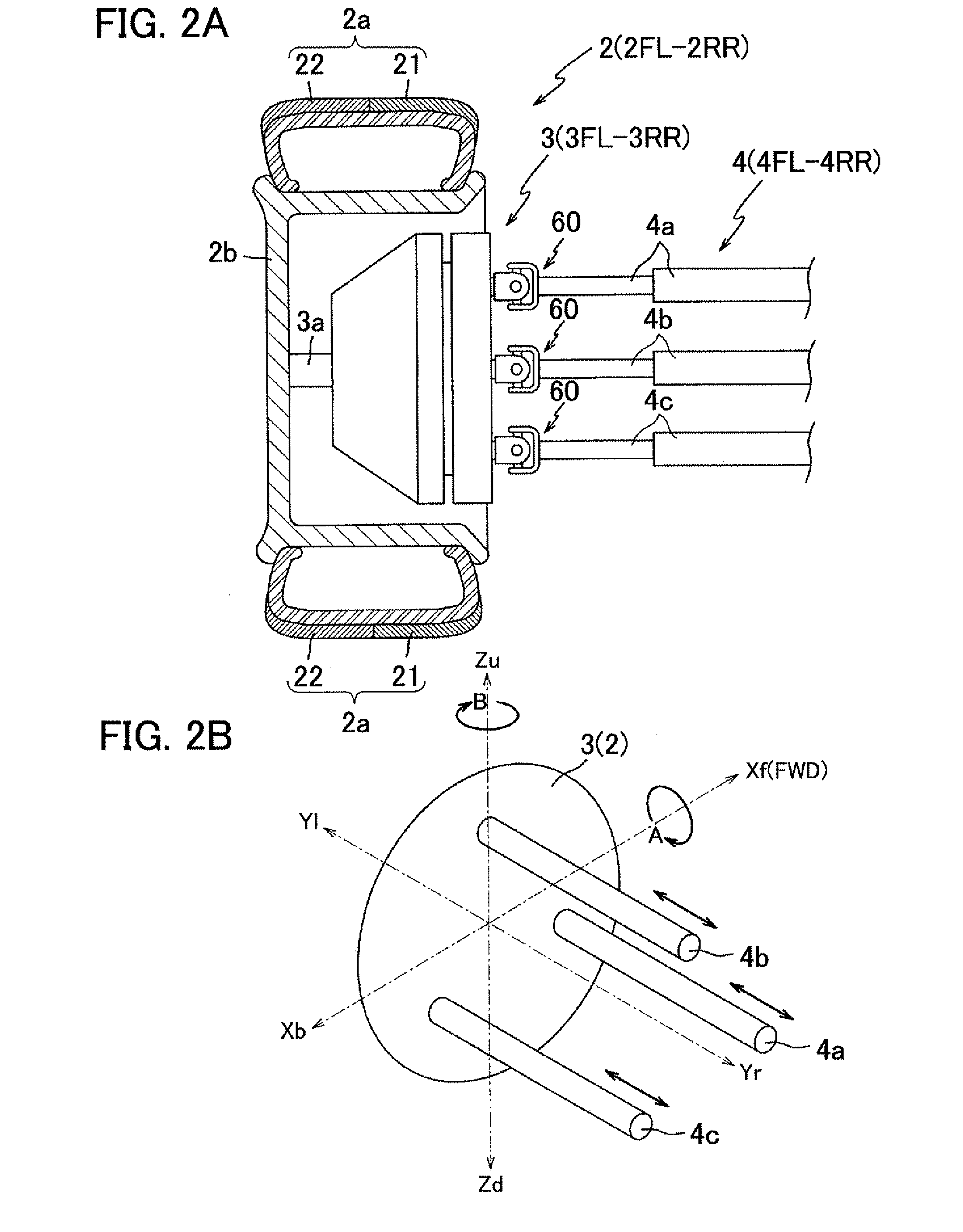
[0266]As shown in FIG. 15, the wheel 202 is composed of only the first tread 21. Note that the wheel 202 is not necessarily composed of only the first tread 21 but may be composed of only the second tread 22.

[0267]Next, a camber angle map according to the second embodiment will be described with reference to FIG. 16. FIG. 16 is a schematic diagram schematically illustrating a content of the camber angle map according to the second embodiment. Note that the camber angle map shown in FIG. 16 is based on actual measurement values measured with respect to the wheel 202.

[0268]The CPU 71 determines a camber angle to be applied to the wheel 202 based on the content of this camber angle map. Note that, in FIG. 16, solid lines 201 and 202 correspond to the coefficient of friction and the rolling resistance, respectively. Although the camber angle map stores three types of maps corresponding to the three operating states of the road surface condition switch 55, FIG. 16 illustrates only one t...

third embodiment

[0287]As shown in FIG. 18, the vehicle 301 is provided with the engine 303 that rotationally drives some or all of the wheels 2 (left front wheel 2FL and right front wheel 2FR in the present embodiment).

[0288]The engine 303 is an engine for burning fuel such as gasoline or diesel oil and converting the thermal energy thus generated to power, and structured so as to be capable of applying the power to the wheels 2 (left front wheel 2FL and right front wheel 2FR) through drive shafts (not shown). A vehicular control device 300 feeds the fuel to the engine 303.

[0289]Next, a detailed structure of the vehicular control device 300 will be described with reference to FIG. 19. FIG. 19 is a block diagram showing an electrical configuration of the vehicular control device 300. As shown in FIG. 19, the vehicular control device 300 is provided with a fuel feeding device 336 and a fuel sensor device 335.

[0290]The fuel feeding device 336 is a device for feeding fuel (such as gasoline or diesel o...


PUM


Abstract

A camber angle applying device is controlled to adjust the camber angle of wheels to a predetermined value. Therefore, the characteristics (or a high gripping property) of a high gripping force and the characteristic (or a low rolling resistance) of a small rolling resistance can be separately used as the performance of the wheels. By utilizing the high gripping property of the wheels, therefore, a vehicle is enabled to reduce its energy consumption, while retaining its running characteristics (such as a turning performance, an accelerating performance or a braking performance), by utilizing the rolling resistance of the wheels. Moreover, the camber angle applying device is controlled to reduce the rolling resistance of the wheels, so that the energy loss to occur in the wheels during running can be reduced to further reduce the energy consumption of the vehicle.

Description

TECHNICAL FIELD[0001]The present invention relates to a camber angle controlling device that controls a camber angle applying device applying camber angles to wheels of a vehicle, and particularly to a camber angle controlling device that is capable of reducing the energy consumption of a vehicle while ensuring the running performance thereof.BACKGROUND ART[0002]It has been attempted to bring out the performance of a tire by setting a camber angle of a wheel (angle formed by a wheel center and a traveling road surface) to a value in the negative direction so as to ensure the running performance of a vehicle. The reason for this is that, if, for example, the camber angle is set to zero degrees, the wheel lifts from the road surface because a vehicle body rolls during turning, and thus the gripping force of the tire cannot be brought out sufficiently. Therefore, by setting the camber angle to a value in the negative direction in advance so as to prevent the wheel from lifting, the gri...

Claims


Application Information

Patent Timeline
Patent Type & Authority Applications(United States)
IPC IPC(8): G06F19/00
CPCB60C3/06B60C11/00B60C11/0083B62D17/00B60G7/006B60G2200/46B60C19/001Y02T10/86B60C11/0058B60C11/0066
Inventor NAITO, TAKASHIANDO, MASAOHASEBE, MASAHIROHORIGUCHI, MUNEHISAMIZUNO, AKIRAKAMIYA, HITOSHIJONES, MICHAEL
Owner EQUOS RES
Why Eureka
Try Eureka