Modulation method and apparatus for dimming and/or colour mixing utilizing leds

a technology of leds and modules, applied in the direction of electric variable regulation, process and machine control, instruments, etc., can solve the problems of limiting the maximum high frequency of leds, affecting the operation of leds, and requiring a wide dynamic frequency rang

Active Publication Date: 2007-05-10
MATE
View PDF30 Cites 113 Cited by
  • Summary
  • Abstract
  • Description
  • Claims
  • Application Information

AI Technical Summary

Benefits of technology

[0013] It is an object of the present invention to obviate or mitigate at least one disadvantage of previous methods of modulation for controlling loads, such as LEDs.

Problems solved by technology

However, when performing PWM in the digital domain (DPWM), problems occur when the system is operating at a low intensity.
However, this technique suffers from the problem that a wide dynamic frequency range is required for the dimming current to achieve an acceptable range of light intensities.
Electromagnetic compatibility (EMC) issues limit maximum high frequency for LEDs.
It is also possible to vary the intensity of an LED by varying the amount of current passing through it but this can lead to a problems such as colour shifting.

Method used


Image

  • Modulation method and apparatus for dimming and/or colour mixing utilizing leds
  • Modulation method and apparatus for dimming and/or colour mixing utilizing leds
  • Modulation method and apparatus for dimming and/or colour mixing utilizing leds

Examples


first embodiment

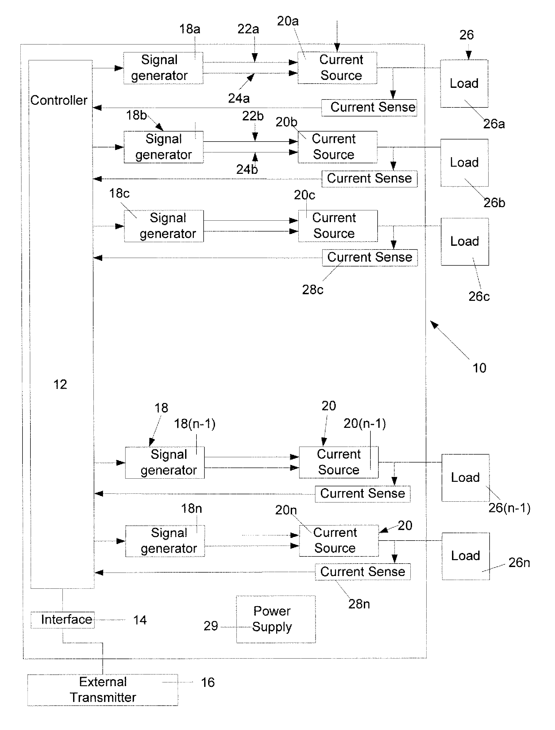
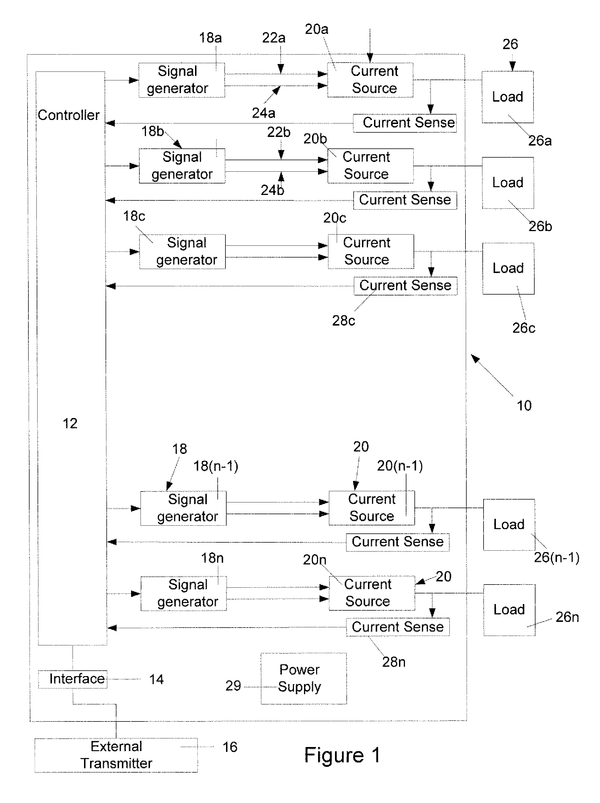
[0027] Turning to FIG. 1, a schematic diagram of apparatus for dimming and / or colour mixing LEDs is shown. The apparatus 10 comprises a controller 12 which is used to control the operation of a plurality of loads 26, such as LEDs. The apparatus 10 further comprises an interface 14 which is in communication with the controller 12. The interface 14 serves to connect the apparatus 10 to an external processor or transmitter 16, such as a DMX512A transmitter. As will be understood DMX512A is a method of digital data transmission between controllers and control equipment. It is designed to carry repetitive control data from a single controller (transmitter) to one or more receivers. The interface 14 receives signals, in the form of data packets, from the transmitter 16 containing dimming and / or colour mixing information for the apparatus 10. The data packets are then transmitted from the interface 14 to the controller 12.

[0028] The controller 12 is also connected to a plurality of signal ...

second embodiment

[0042] Turning to FIG. 5, apparatus for dimming and / or colour mixing LEDs is shown. In this further embodiment, each of the loads are controlled by individual load controllers 30, individually denoted as 30a to 30n. The functionality of the controller 12 is split between a main controller 32 and individual load controllers 30. All other parts are identical to the embodiment of FIG. 1 and are denoted as such.

[0043] The main controller 32 receives the dimming and / or colour mixing information, in the form of a serial data stream, from the external transmitter 16 via the internal interface 14 and translates this information to controller information, in the form of a more easily decoded synchronous data stream, and transmits this controller information to the individual load controllers 30a to 30n. This simplified controller information, or words of data, is preferably transmitted over a shared “sync” line, a shared “clock” line and a set of parallel “data” lines. The start of each word...


PUM


Abstract

There is provided apparatus for controlling a set of light emitting diodes (LEDs) comprising at least one current source for powering the set of LEDs; a main controller for receiving dimming and/or colour mixing information and for translating the information into LED control information and transmitting the LED control information to control the set of LEDs; wherein the LED control information is based on on and off times.

Description

CROSS REFERENCE TO RELATED APPLICATIONS [0001] This application claims the benefit of priority of U.S. Provisional Patent Application No. 60 / 735,220 filed Nov. 10, 2005, and U.S. Provisional Patent Application No. 60 / 796,550 filed May 2, 2006, which are incorporated herein by reference.FIELD OF THE INVENTION [0002] The present invention relates generally to controlling LEDs. More particularly, the present invention relates to a method and apparatus for dimming and / or colour mixing LEDs. BACKGROUND OF THE INVENTION [0003] In the field of lighting technology, there are many different ways for an individual to provide light to a space, such as a room in a house. In the past, lighting levels were limited to only two positions, namely ON and OFF. Therefore, when a person wished to light up the space, they simply turned the light on. In the more recent past, in order to allow individuals to control the amount of lighting in a space, and to assist in lowering the cost to power the lighting...

Claims


Application Information

Patent Timeline
Patent Type & Authority Applications(United States)
IPC IPC(8): H05B37/02B60Q1/124H05B44/00
CPCH05B33/0818H05B33/0866Y02B20/347H05B45/24Y02B20/30H05B45/375
Inventor NEUDORF, JASON CHRISTOPHER JOHNLYONS, STEVETIKKANEN, DAVID
Owner MATE
Why Eureka
Try Eureka