Asymmetric Differential Timing

a technology of differential timing and clock timing, applied in the field of clock timing in telecom networks, can solve the problems of increasing the price adding a pll device to the differential timing design, and reducing the applicability to various deployment scenarios, so as to simplify the cost and complexity of the system, reduce the cost and complexity, and reduce the cost of the system. the effect of complexity

Inactive Publication Date: 2007-05-10
RESOLUTE NETWORKS
View PDF2 Cites 13 Cited by
  • Summary
  • Abstract
  • Description
  • Claims
  • Application Information

AI Technical Summary

Benefits of technology

[0018] The differential timing solution provided herein relieves the need for a frequency conversion device such as a PLL by relaxing the requirement for symmetric operation. Instead of using a PLL device as in current practice, a controller included in each subsystem uses arithmetic operations to accommodate the asymmetry of the solution. Arithmetic operations require fewer resources from the system (e.g. can be done in software) and no accuracy is lost. Therefore the present invention simplifies the cost and complexity of systems using the differential timing method without limiting the applicability of the solution only to symmetric deployment scenarios.
[0019]

Problems solved by technology

The need to add a PLL device to a differential timing design adds cost and complexity.
The main disadvantage of the current practice symmetric systems and methods is that such systems must use a frequency conversion device (e.g. a PLL) to convert between the possible common clock frequencies in order to support real life deployment scenarios.
Frequency conversion between high frequency clocks

Method used


Image

  • Asymmetric Differential Timing
  • Asymmetric Differential Timing
  • Asymmetric Differential Timing

Examples


Embodiment Construction

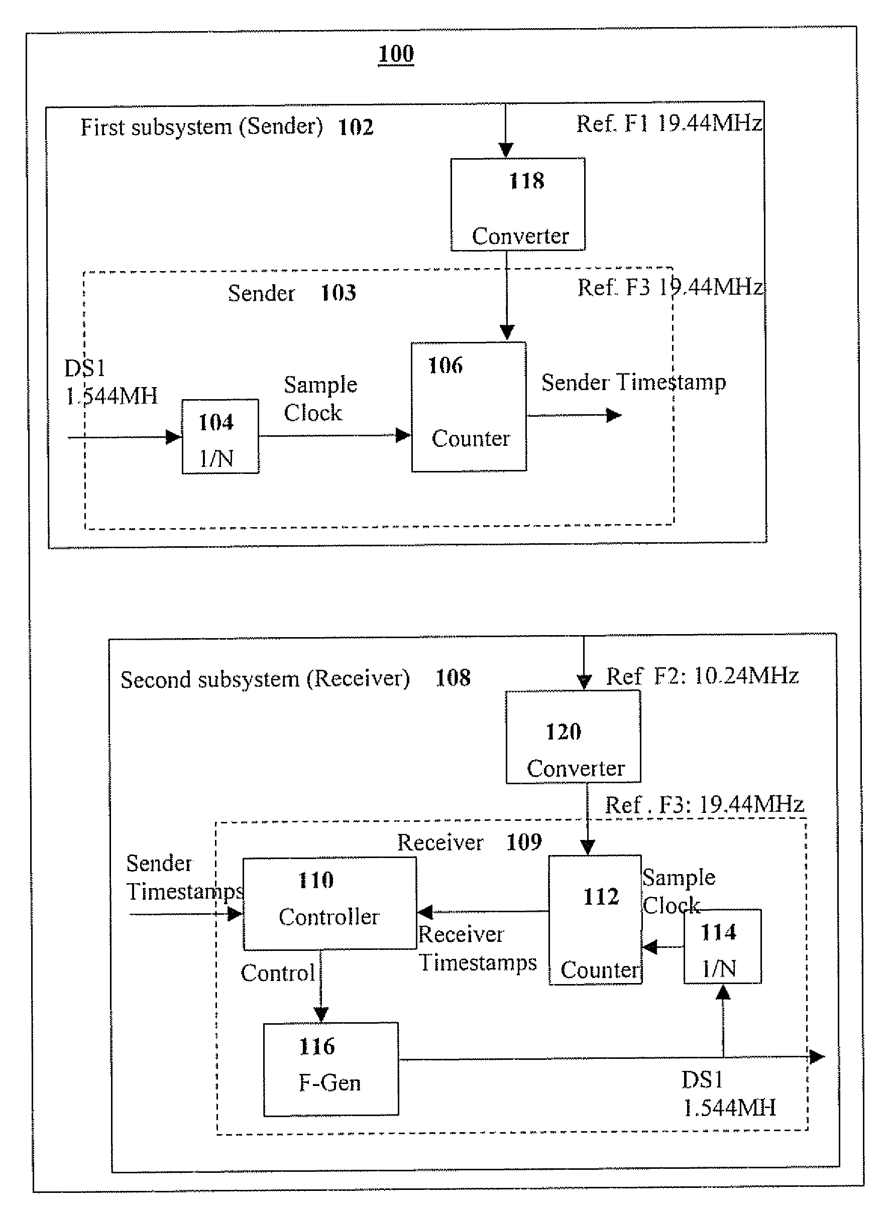
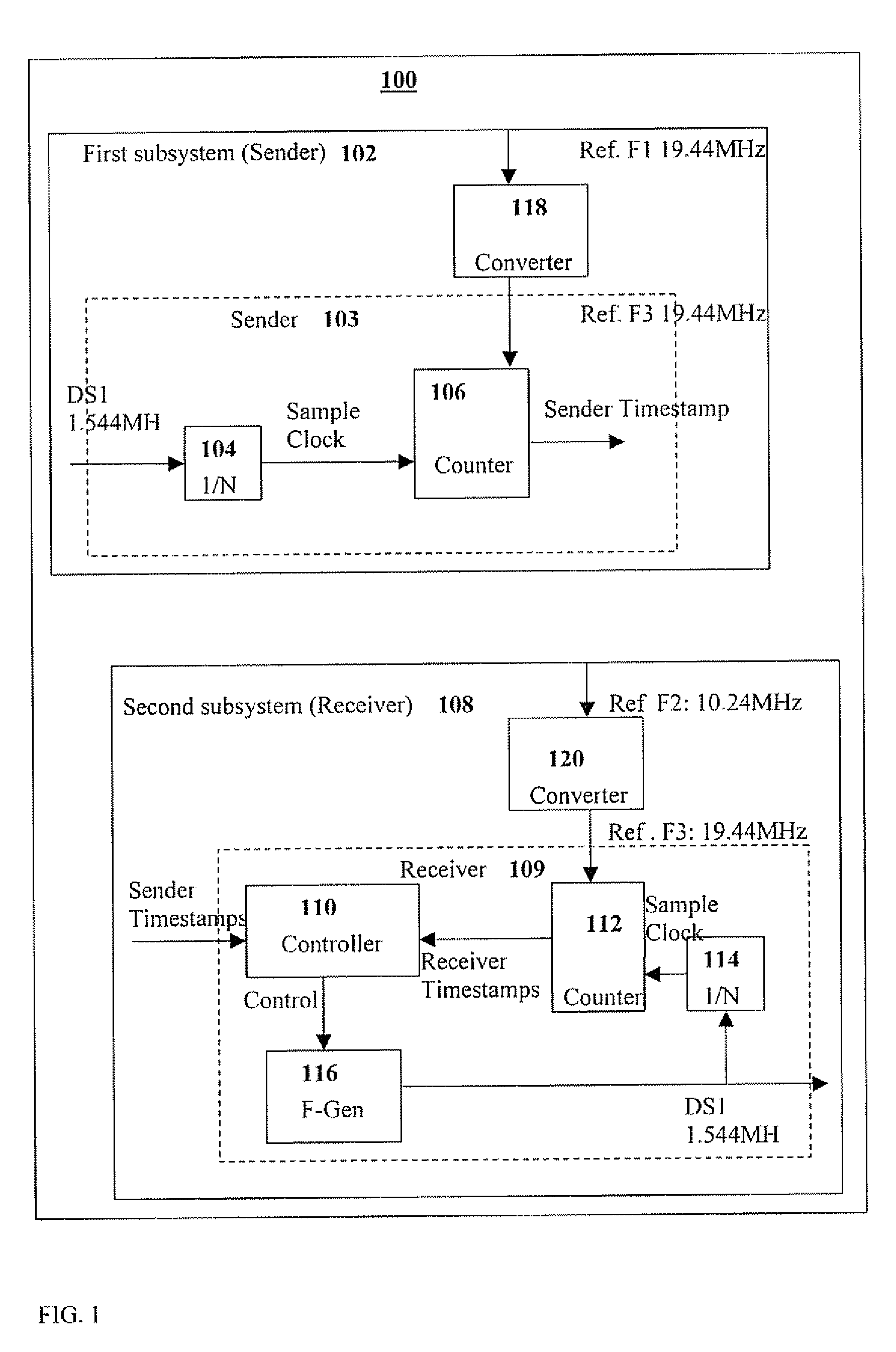
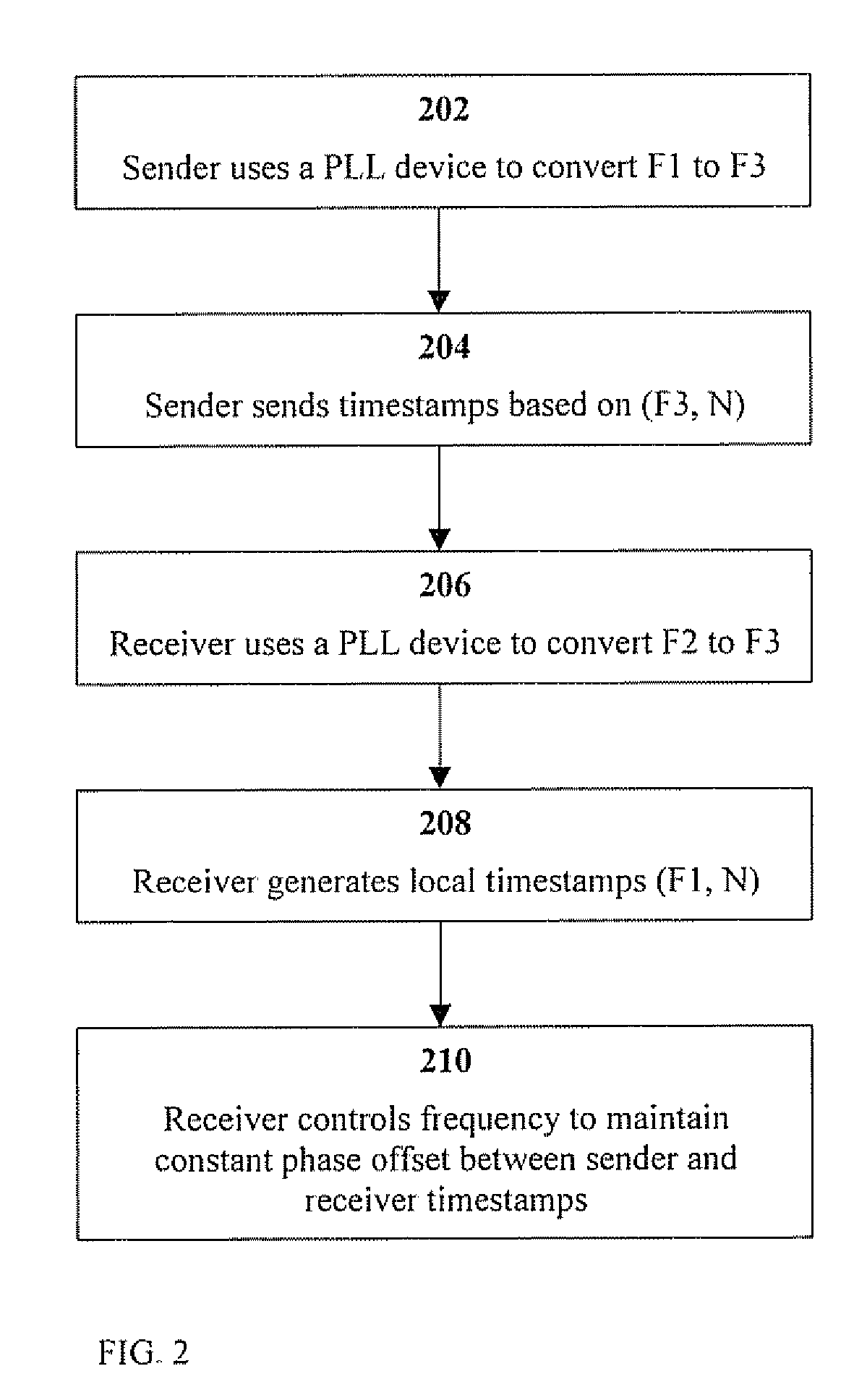
[0027] The present invention discloses an asymmetric differential timing solution in which receiver and sender in each “subsystem” as defined above use the highest available clock frequency traceable to the same source for time-stamping and in which no PLL is required to convert between different frequencies. FIG. 3 describes the main steps of one embodiment of the asymmetric differential timing method of the present invention. In step 302, a sender in a first subsystem uses a clock traceable to a common clock source with highest frequency and accuracy available to it (frequency F1) for time-stamping N cycles of a ‘service clock’, In step 304, a receiver in a second subsystem uses a clock traceable to a common clock source with highest frequency and accuracy available to it (second frequency F2) to generate local timestamps of M cycles of a locally generated ‘service clock’. In step 306, the receiver aligns local (receiver) timestamps and timestamps received from the sender to the s...


PUM


Abstract

A system and method for reconstructing a service clock between two, first and second subsystems communicating therebetween, comprising a first subsystem operative to generate first subsystem timestamps, a second subsystem operative to generate second subsystem timestamps at a second frequency different from the first timestamps, wherein the generations of both first and second timestamps are based on sampling of the service clock by a common clock available at both subsystems, and an aligner for arithmetically aligning the different first and second subsystem timestamps to reconstruct the service clock.

Description

CROSS REFERENCE TO RELATED APPLICATIONS [0001] The present invention claims priority from U.S. Provisional Patent Application No. 60 / 734,781 filed Nov. 9, 2005, the content of which is incorporated herein by reference.FIELD OF THE INVENTION [0002] The present invention relates generally to clock timing in telecom networks, and more particularly to differential timing in such networks. BACKGROUND OF THE INVENTION [0003] Telecom networks are built to deliver data and clock (the latter referred to as ‘service clock’) from one end of the network to the other. Strict standards for the stability of the clock at the output of a telecom network are in place to guarantee the quality of the service delivered at the end points. A collection of methods called ‘differential timing’ can be used to deliver the service clock from one end of the network to the other, when both ends of the network have access to a stable clock traceable to the same source (referred to as a ‘common clock’). [0004] An ...

Claims


Application Information

Patent Timeline
IPC IPC(8): H04J3/06
CPCH04J3/0691
Inventor COHEN, RONGAL-ON, BARPELEG, ZOHARBRIEF, DAVID
Owner RESOLUTE NETWORKS
Why Eureka
Try Eureka