Reversing sensor without a control box

Inactive Publication Date: 2007-05-17
COLIGEN CHINA
View PDF9 Cites 1 Cited by
  • Summary
  • Abstract
  • Description
  • Claims
  • Application Information

AI Technical Summary

Benefits of technology

[0008] The present invention provides a reversing sensor without a control box for a vehicle, which applies a master-slave type of sensor architecture. With the reversing sensor without the control box of the present invention, the control box of a reversing device can be eliminated and the device can also be tested for problems before assembling. Furthermore, with the present invention, line material costs can be reduced.
[0009] In order to achieve the above-mentioned objectives, the reversing sensor device for a vehicle of the present invention includes at least one master-sensor and more than one slave-sensor. The master-sensor includes a microprocessor, an ultrasonic emission circuit, a reflective wave detection circuit and an alarm circuit. The master-sensor not only takes charge of detecting the obstacle but can also coordinate the operation timing for each of the slave-sensors. In this way, the master-sensor replaces the functionality of a conventional control box. The master-sensor is connected to the slave-sensors and also uses a time-sharing principle and a polling method to control the timing of each slave-sensor to collect a detection result. In addition, the slave-sensor includes a microprocessor, an ultrasonic emission circuit and a reflective wave detection circuit. Since the master-sensor and the slave-sensors are installed on a vehicle's rear bumper, when a vehicle is assembled in a factory, the reversing sensor can be easily tested on the bumper without having to attach the rear bumper to the vehicle. Hence testing procedures can be further improved.

Problems solved by technology

Therefore line material cost is rather high and also the long data line is likely to be affected by interference.
On the other hand, there is also a problem when testing parts of a vehicle and assembling the vehicle.
Hence it is rather inconvenient for installation and testing operations, so as to reduce production efficiency.

Method used


Image

  • Reversing sensor without a control box
  • Reversing sensor without a control box
  • Reversing sensor without a control box

Examples


Embodiment Construction

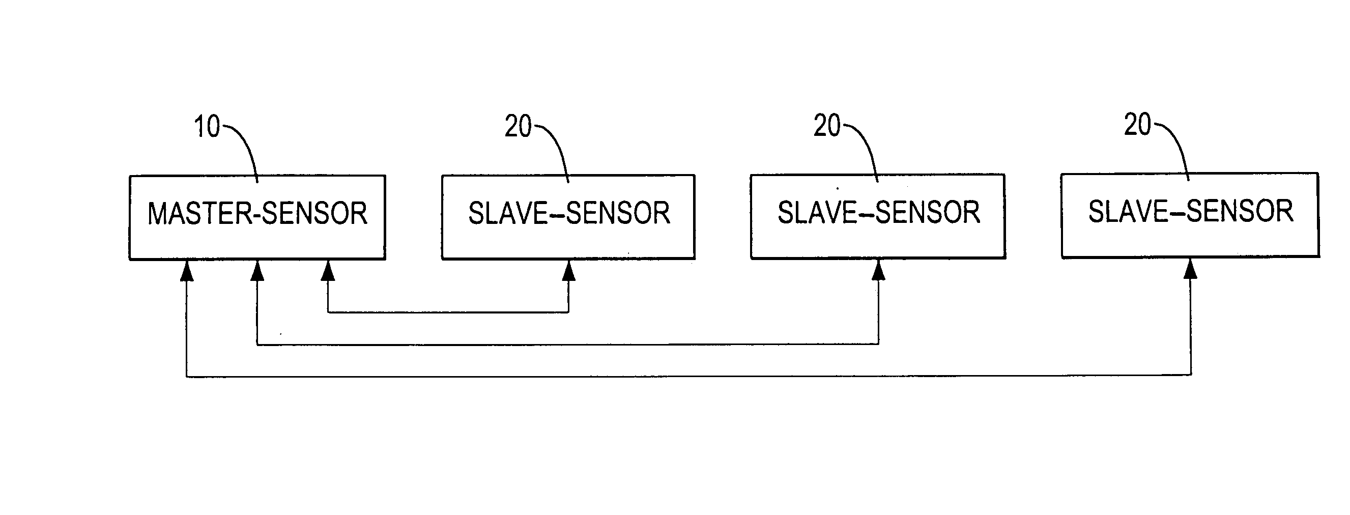
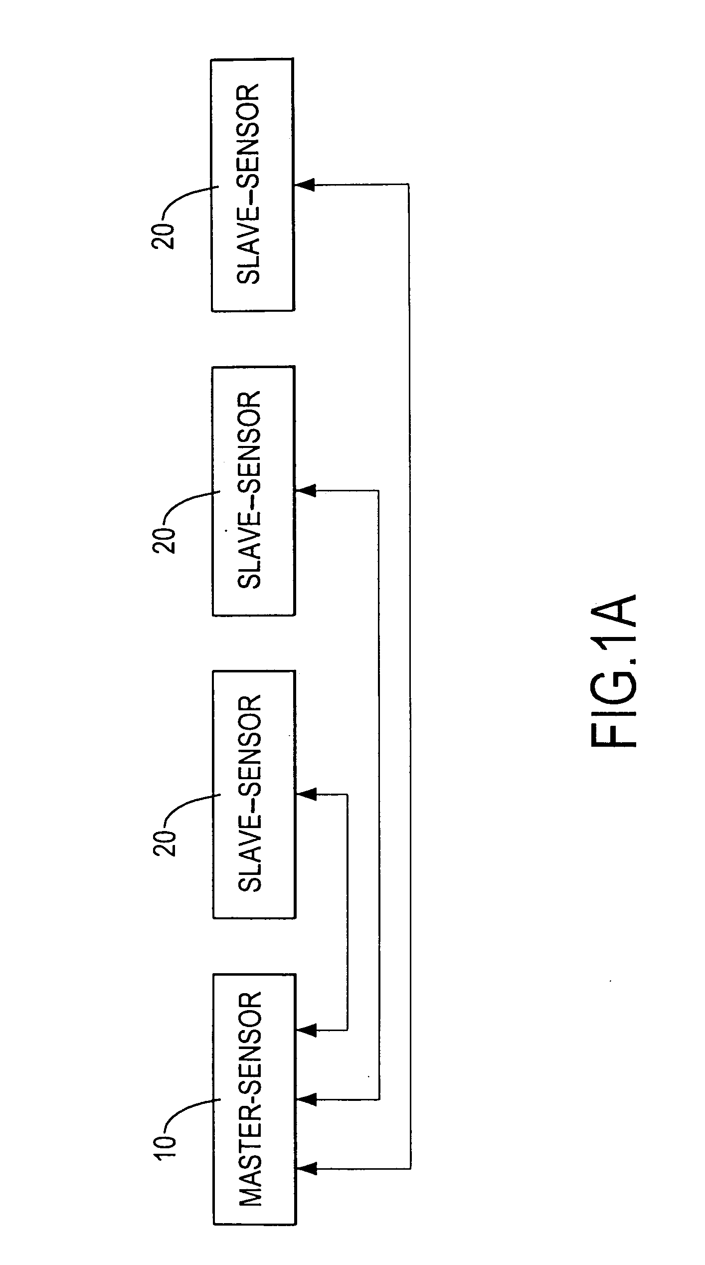
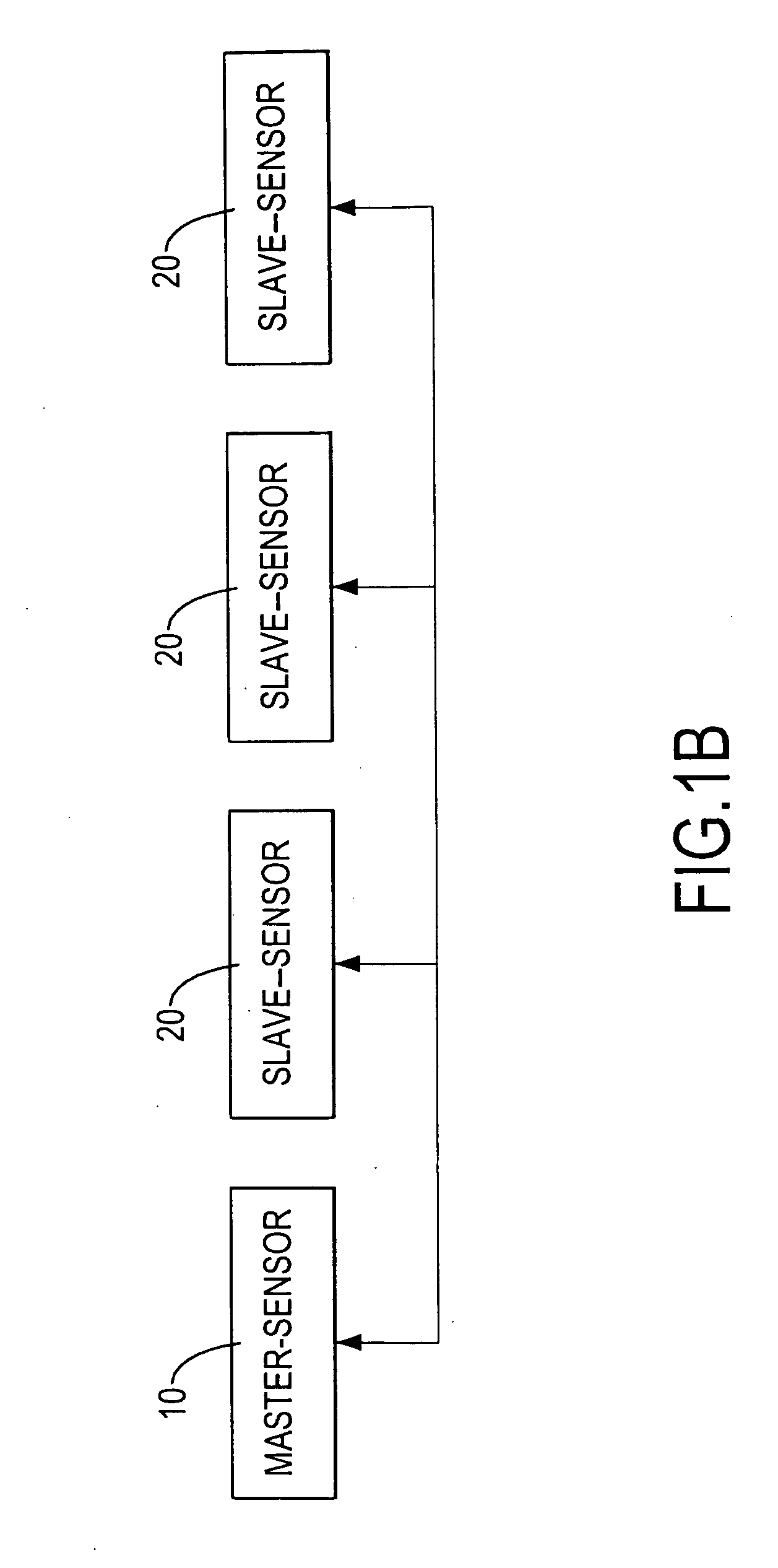
[0015] With reference to either FIGS. 1A or 1B, a system block diagram of the present invention mainly comprises a master-sensor 10 and multiple slave-sensors 20. Each slave-sensor 20 is respectively connected to the master-sensor 10 via an independent line and also communicates with the master-sensor 10. Moreover, the slave-sensors 20 can also be mutually connected to the master-sensor 10 via a single communication line. No matter how the master sensor 10 is connected to the slave-sensors 20, the master-sensor 10 uses a polling method to control the timing of each slave-sensor 20 to collect a detection result. Each slave-sensor 20 sends detection data to the master-sensor 10 only when the slave-sensor 20 receives a polling instruction from the master-sensor.

[0016] A detailed circuit diagram of a practicable example of a preferred embodiment of the master-sensor 10 is shown in FIGS. 2A-2D. The master-sensor 10 includes a microprocessor U1, an ultrasonic emission circuit 12, a refle...


PUM


Abstract

A reversing sensor device applies a master-slave type of sensor architecture. The reversing sensor device includes at least one master-sensor and more than one slave-sensor. The master-sensor includes a microprocessor, an ultrasonic emission circuit, a reflective wave detection circuit and an alarm circuit. The master-sensor not only takes charge of detecting the obstacle but can also coordinate the operation timing for each of the slave-sensors. In this way, the master-sensor replaces the functionality of a conventional control box. The master-sensor is connected to the slave-sensors and also uses a time-sharing principle and a polling method to control the timing of each slave-sensor to collect a detection result. In addition, the slave-sensor includes a microprocessor, an ultrasonic emission circuit and a reflective wave detection circuit.

Description

BACKGROUND OF THE INVENTION [0001] 1. Field of the Invention [0002] The invention relates in general to a reversing sensor without a control box, and more particularly a master-slave type of sensor architecture to form a reversing sensor for a vehicle, wherein a master-sensor not only can take charge of detecting an obstacle but also can coordinate an operation timing for each slave-sensor and collect a detection result of the slave sensors. [0003] 2. Description of the Related Art [0004] Among quickly developing technology, reversing sensors for automobiles are becoming widely used to assist drivers in backing up a vehicle safely. The sensitivity of a reversing sensor is directly related to a configuration setting and the number of sensors used. [0005] With reference to FIG. 4, a conventional reversing sensor having multiple sensors includes a control box 80 connected to multiple ultrasonic sensors 81˜84. Each of the multiple ultrasonic sensors 81˜84 is connected to the control box...

Claims


Application Information

Patent Timeline
IPC IPC(8): B60Q1/00
CPCB60Q9/006G01S7/523G01S15/87G01S15/931
Inventor LI, SHIH-HSIUNG
Owner COLIGEN CHINA
Why Eureka
Try Eureka