
Tooth implant

a technology for teeth and support posts, applied in dental surgery, medical science, dentistry, etc., can solve the problems of re-installation and problematic removal of support posts from base carriers, and achieve the effects of large engagement force, easy re-installation, and large frictional area

Inactive Publication Date: 2007-05-17
LAUX ROBERT
View PDF10 Cites 19 Cited by
  • Summary
  • Abstract
  • Description
  • Claims
  • Application Information

AI Technical Summary

Benefits of technology

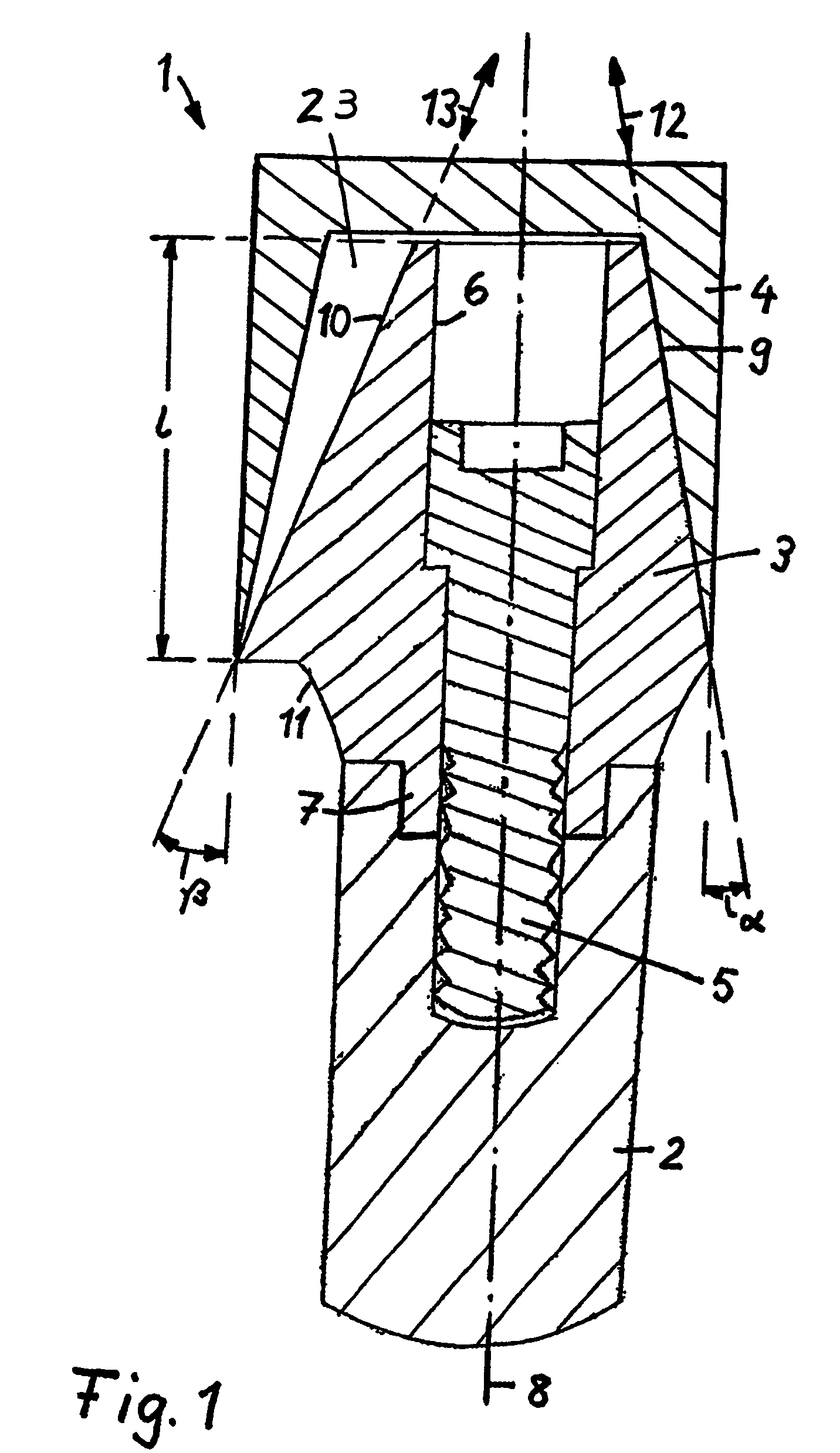
[0016] If the part with the two different sectors is surrounded by the second part, the cavity is disposed between the longitudinal axis of the base carrier and the cone-shaped rotationally symmetrical envelope defined by the friction cone sector. The second sector is recessed in the longitudinal direction with respect to the envelope defined by the friction cone sector, whereby the cavity is formed. This cavity makes it possible to install and remove the implant part cooperating with the first implant part in a direction which deviates from the longitudinal axis of the first implant part. The installation or, respectively, removal direction of the second implant part does not need to coincide with the longitudinal axis of the second implant part either.
[0021] Another advantage is that also with a subsequent change of the tooth implant for example if the crown or the support post become unintentionally loose, the desired installation position can be re-established at any time without substantial additional efforts. On one hand, a very accurate re-orientation of the crown after removal and re-installation is possible but, on the other hand, not absolutely necessary for a secure connection while maintaining an angle divergence between the longitudinal implant axis and the installation direction since each sector extends over a larger circumferential angle so that, with a position change of the crown of only a few degrees, a collision-free installation of the crown is generally still possible.
[0025] The implant part, particularly the support post may include in a front area an axially projecting multi-edge connecting section for example a hexagonal connecting section which can be inserted into a complementarily shaped recess in the adjacent component of the tooth implant—usually in the base carrier. This multi-edge connection provides only for a limited number of angular positions of the respective implant part wherein the number of angular positions depends on the number of edges of the multi-edge connecting section. In the exemplary embodiment of a hexagon, the respective implant can be installed in six different angular positions which differ by 60°. In case of a subsequent machining of the tooth implant for which the tooth implant needs to be removed, it can easily be re-installed in the desired angular position since the asymmetric shape provided by differently shaped sectors in the support post of the implant offers sufficient reference points for re-installation in the correct 60° angle position.
[0026] One of the sectors has the function of a friction cone sector which has a conical geometry with a cone angle which is expediently in a range of 1° to 9°, particularly about 4°. The friction cone sector provides for a frictional jointure with the adjacent implant part which includes a complementary abutment surface which engages the friction cone sector and forms a frictional jointure therewith. Expediently, the friction cone sector extends in circumferential direction at least over 180° of the support post so as to provide for a sufficiently large frictional area and, consequently, a jointure with a sufficiently large engagement force.
[0027] The second sector has the function of an accommodation sector which, because of its different inclination angle facilitates the accommodation of an angle divergence between the longitudinal axis of the base body and the installation or, respectively, removal direction.

Problems solved by technology

However, the later removal of the support post from the base carrier and its re-installation is problematic since the accurate angular position of the support post has to be re-established.
In the arrangement according to U.S. Pat. No. 5,439,380, it is disadvantageous that there are only six angular position at angular distances of 60°, which are determined by a hexagonal connection between the support post and an underlaying hexagonal connecting part.

Method used


Image

  • Tooth implant
  • Tooth implant
  • Tooth implant

Examples


Embodiment Construction

[0051] Identical components are designated in the various figures by the same reference numerals.

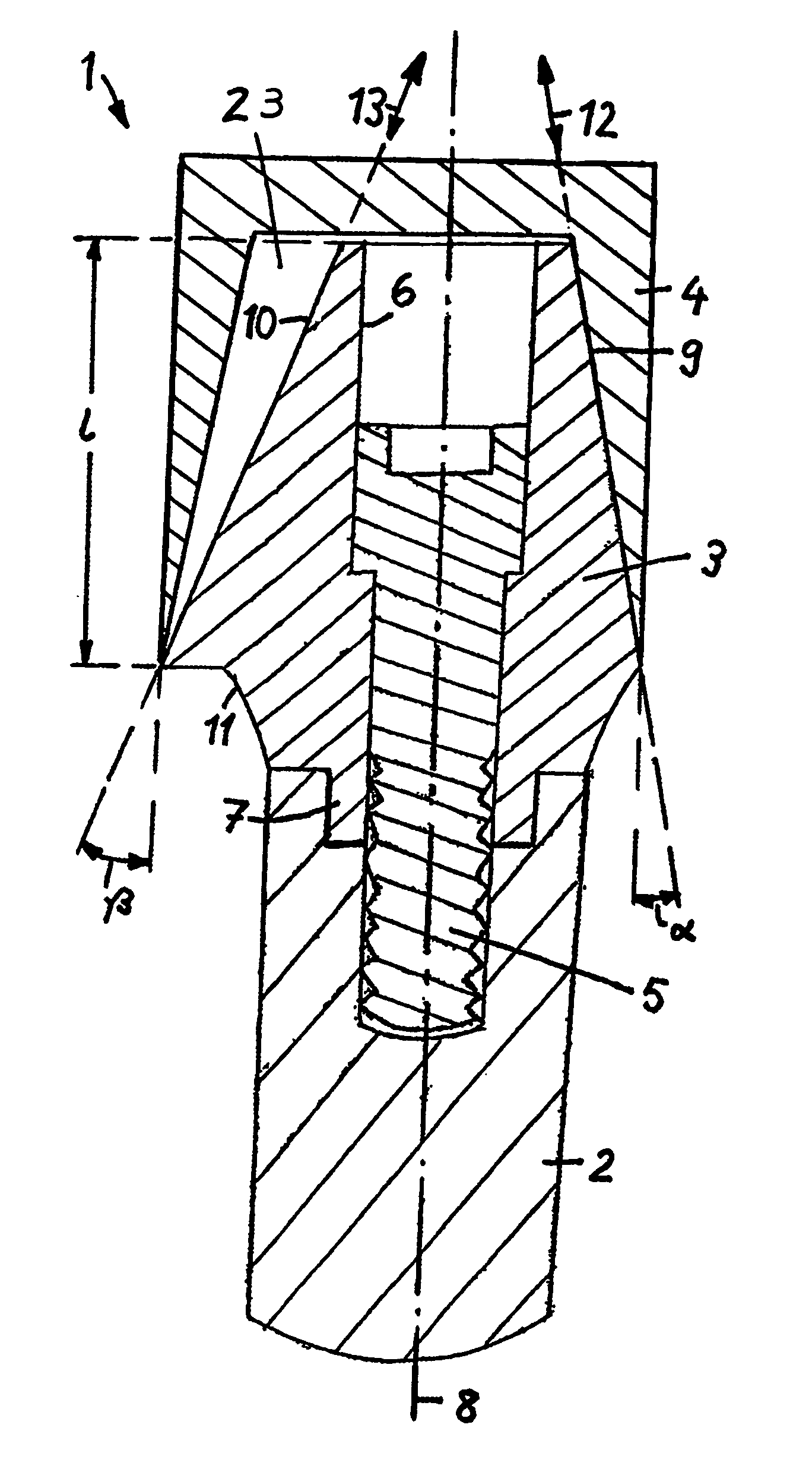
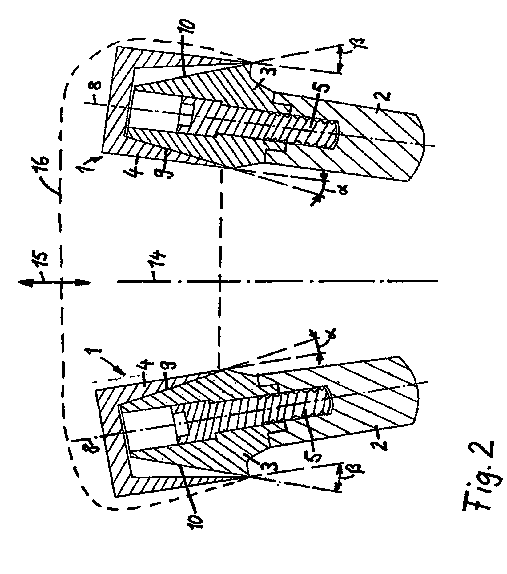
[0052]FIG. 1 shows a tooth implant 1 which comprises a base carrier 2 to be implanted into the jaw of a patient, a support post 3 and a tooth crown 4 disposed on the support post. All components have a common longitudinal axis 9. The support post 3, which is also called the primary crown is disposed on the base carrier 2 and firmly connected thereto by a screw 5. The screw 5 extends into a central bore 6 in the support post 3 and is screwed into a threaded complementary bore formed in the base carrier 2. For better mounting the support post 3 has in the area of its lower front end, a multi-edge connecting section 7, preferably in the form of a hexagonal connecting section, which is received in a complementary cavity formed in the adjacent top end of the base carrier 2. The connecting section 7 may also be in the form of a cone-shaped or cylindrical projection.

[0053] The crown 4 is conn...


PUM


Abstract

In a tooth implant for mounting onto an implant base carrier (2), including a support post and a crown releasably disposed on the support post, wherein the support post has a cone-shaped base body with at least a friction cone sector and an accommodation sector which, with respect to a rotationally symmetrical enveloping area as defined by the cone sector, forms a cavity under the crown upper and lower edge areas where the crown is in contact with the base body, the friction cone sector and a connecting line extending between upper and lower edge areas of the accommodation sector have, in a plane receiving the longitudinal axis of the support post, different inclination angles with respect to the longitudinal axis of the support post.

Description

[0001] This is a Continuation-In-Part Application of International Application PCT / EP2005 / 003834 filed Apr. 12, 2005 and claiming the priority of German Application 10 2004 018 512.3 filed Apr. 14, 2004.BACKGROUND OF THE INVENTION [0002] The invention relates to a tooth implant including primary and secondary crown parts which are releasably joined and one is in the form of a cone-shaped support post including a friction cone section. [0003] WO 01 / 50977 A1 discloses a tooth implant which comprises a base carrier member which is to be implanted into the jaw of a patient and onto which a support post is mounted which carries the tooth crown. The support post comprises two parts, an upper post part and a lower post part, and the two post parts are separated by way of inclined separation plane which defines with the longitudinal axis of the support post an angle different from 90°. The two post parts can be combined in different angular positions with respect to the longitudinal axis of...

Claims


Application Information

Patent Timeline
IPC IPC(8): A61C8/00
CPCA61C8/0048
Inventor LAUX, ROBERT
Owner LAUX ROBERT
Learn More