
Liquid cooling for backlit displays

a backlit display and liquid cooling technology, applied in the field of liquid cooling, can solve the problems of significant thermal challenges of traditional cooling methods, high cost and high heat issues of applications, and traditional cooling methods that have difficulty coping with the high heat flux of modern leds

Inactive Publication Date: 2007-05-24
COOLIGY INC
View PDF99 Cites 29 Cited by
  • Summary
  • Abstract
  • Description
  • Claims
  • Application Information

AI Technical Summary

Benefits of technology

[0009] Preferably, the first heat collector is bonded to the backlit device by using a thermal interface material (TIM) layer. The TIM layer typically comprise at least one or more of Indium, a metallic coat, a thermal grease, a thermal pad, and / or a phase change material. In some embodiments, the first heat collector is also fastened to the backlit device by using a mechanical means. The mechanical means of these embodiments typically includes one or more of a screw, a bracket, and / or a clamp.

Problems solved by technology

However, these LED applications generally suffer from high cost and high heat issues.
High power LEDs in turn present significant thermal challenges for traditional methods of cooling.
For instance, traditional methods of cooling have difficulty coping with the high heat flux of modern LEDs.
Traditional heat pipe designs in particular are bulky, which defeats the small and / or thin form factor advantages of many LED applications.
Further, heat pipes are limited in the amount of heat they can move, and also in the distance they can move the heat from the heat source, which negatively impacts the display screen size.

Method used


Image

  • Liquid cooling for backlit displays
  • Liquid cooling for backlit displays
  • Liquid cooling for backlit displays

Examples


Embodiment Construction

[0026] In the following description, numerous details are set forth for purpose of explanation. However, one of ordinary skill in the art will realize that the invention can be practiced without the use of these specific details. In other instances, well-known structures and devices are shown in block diagram form in order not to obscure the description of the invention with unnecessary detail.

[0027] Overview

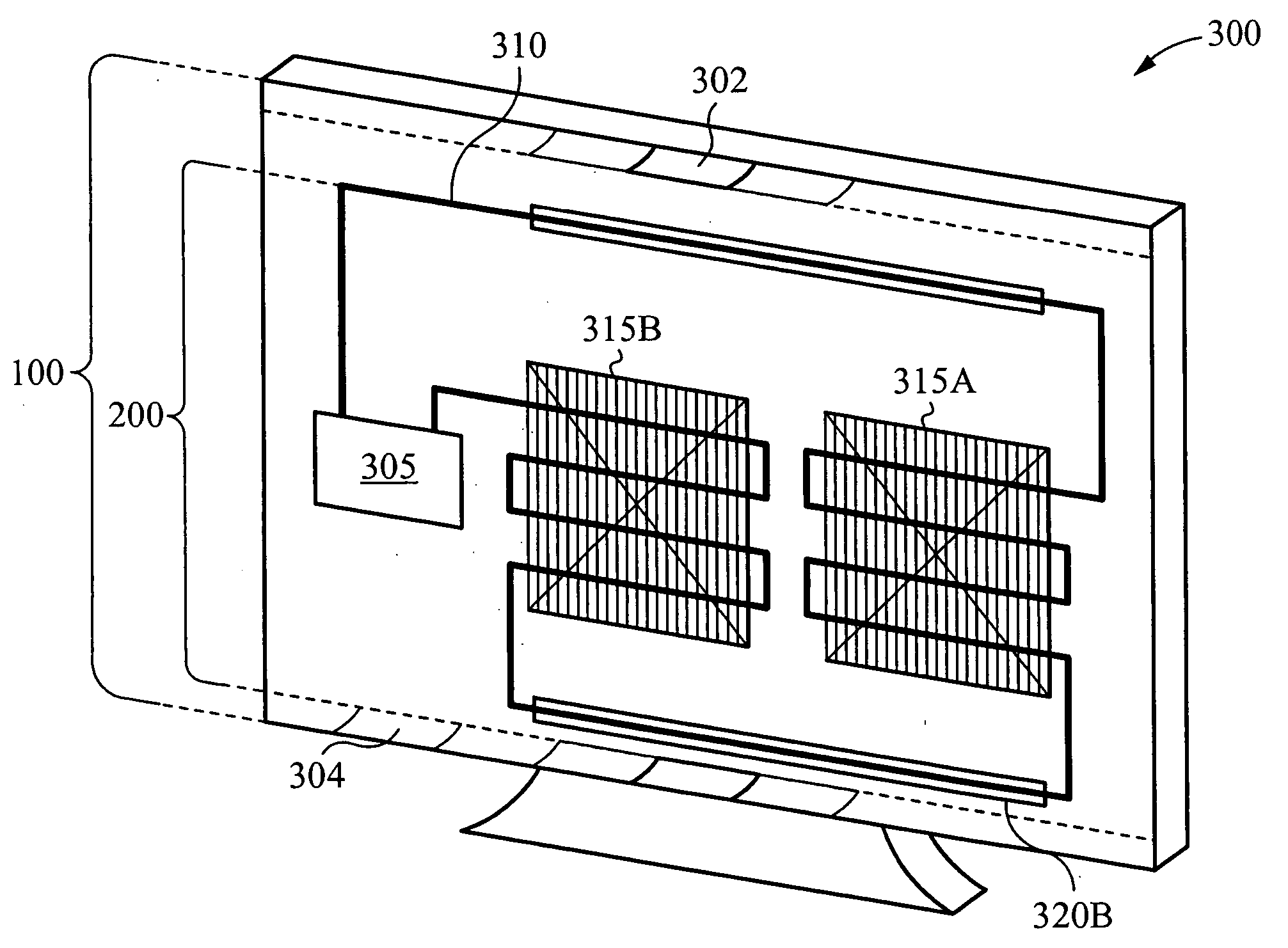
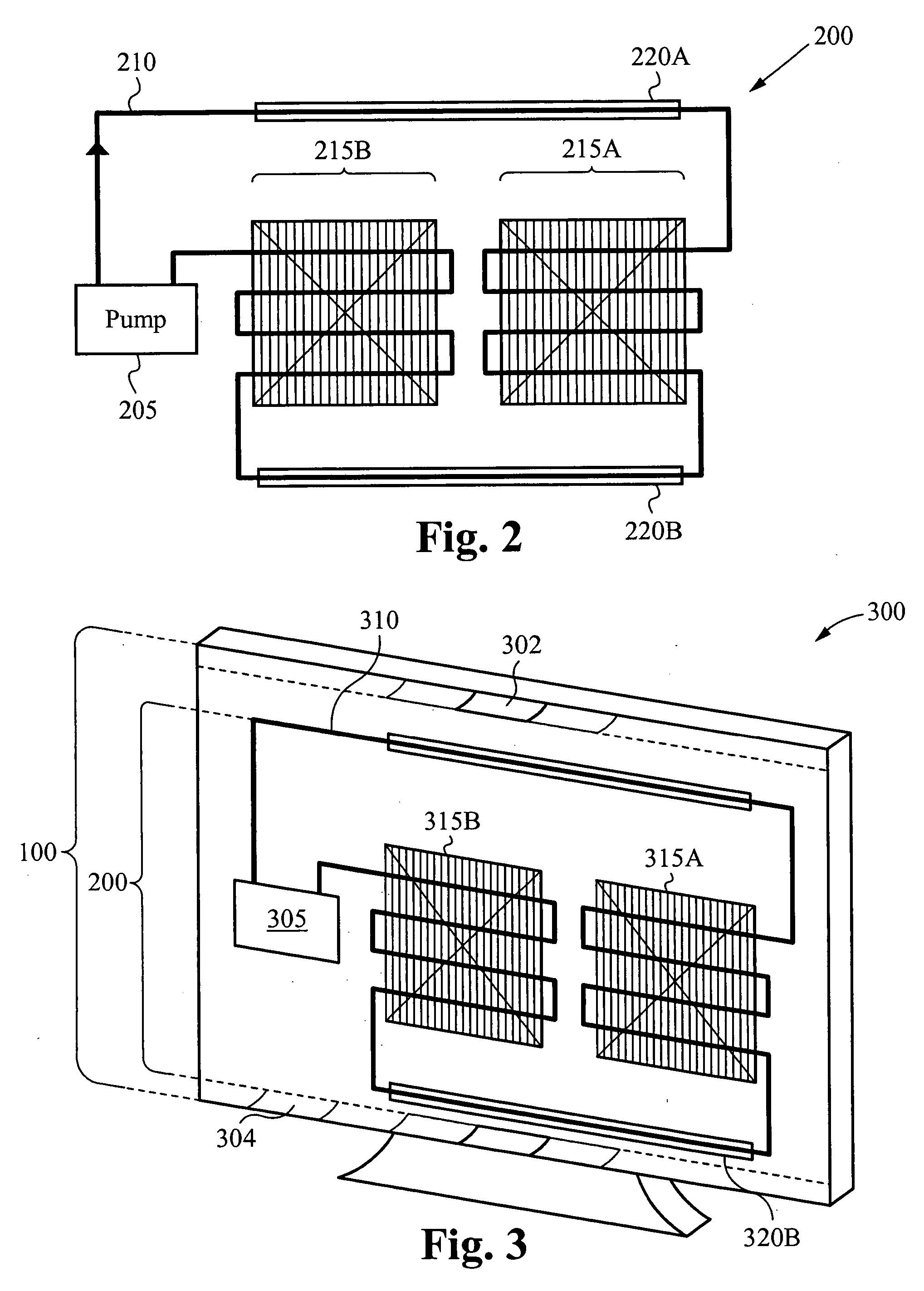
[0028] Some embodiments of the invention provide a liquid cooling system for an LED backlit device, such as, for example, a flat panel display. These embodiments provide cooling to the LEDs of the display without significantly affecting the thin form factor of the device. The cooling system includes: one or more heat collectors; one or more radiator(s), fan(s), and / or fan radiators that have a small form factor; one or more mechanical pumps; tubing and interconnects to couple the elements of the cooling system together, and complete a closed cooling loop.

[0029] The heat colle...


PUM


Abstract

The present invention provides a cooling system for a backlit device. The cooling system has a first heat collector that comprises a micro tube. The first heat collector is for maintaining contact with the backlit device. The cooling system also has a first radiator, a first pump, an interconnecting tubing, a fluid, and optionally a fan and / or a reservoir. The first radiator is for distributing and / or dispersing heat, the first pump is for driving a fluid flow, and the reservoir is for storing the fluid. The interconnect tubing is interposed between the first heat collector, the first radiator, and the first pump to form a closed cooling loop. Some embodiments further provide a method of cooling a backlit device by using such a cooling system.

Description

RELATED APPLICATIONS [0001] This application claims priority under 35 U.S.C. section 119(e) of co-pending U.S. Provisional Patent Application No. 60 / 735,757, filed Nov. 9, 2005, and entitled “Liquid Cooling Systems for Backlit LED Display Products,” which is hereby incorporated by reference.FIELD OF THE INVENTION [0002] The present invention is related to liquid cooling. Specifically, the present invention is related to providing liquid cooling for backlit displays. BACKGROUND OF THE INVENTION [0003] Light emitting diode (LED) technology has been making significant advancement in recent years. The advancement of LED technology has produced numerous applications such as interior and exterior (outdoor) lighting, compact or portable lamps, automotive lights, and also light sources for backlit display systems. In the near future, LED lamps are expected to replace traditional incandescent, halogen, and / or fluorescent lamps (particularly mercury and / or cold cathode flourescent lamps) due ...

Claims


Application Information

Patent Timeline
Patent Type & Authority Applications(United States)
IPC IPC(8): H01L23/467
CPCG02F1/133603G02F2001/133628G06F1/1601G06F1/20G06F2200/1612G06F2200/201G02F1/133628H01L23/467
Inventor UPADHYA, GIRISHMUNCH, MARK
Owner COOLIGY INC
Learn More