Cap structure

a technology of cap structure and cap cap, applied in the field of cap structure, to achieve the effect of easy to miss

Inactive Publication Date: 2007-05-31
LIAO JUNG WEN
View PDF7 Cites 8 Cited by
  • Summary
  • Abstract
  • Description
  • Claims
  • Application Information

AI Technical Summary

Benefits of technology

[0005] It is therefore a primary object of the present invention to provide a cap structure equipped with a glass. The cap structure includes a connecting unit for pivotally connecting the cap body with the glass. The connecting unit can be fixed under a peak section of the cap body by means of magnetic attraction. Therefore, when wearing the cap, a user can also selectively use the glass. When not used, by means of the connecting unit, the glass can be turned upward and folded to attach to the bottom face of the peak section. Moreover, when not used, the glass is still connected with the cap body so that the glass is not easy to miss.

Problems solved by technology

Moreover, when not used, the glass is still connected with the cap body so that the glass is not easy to miss.

Method used


Image

  • Cap structure
  • Cap structure
  • Cap structure

Examples


Embodiment Construction

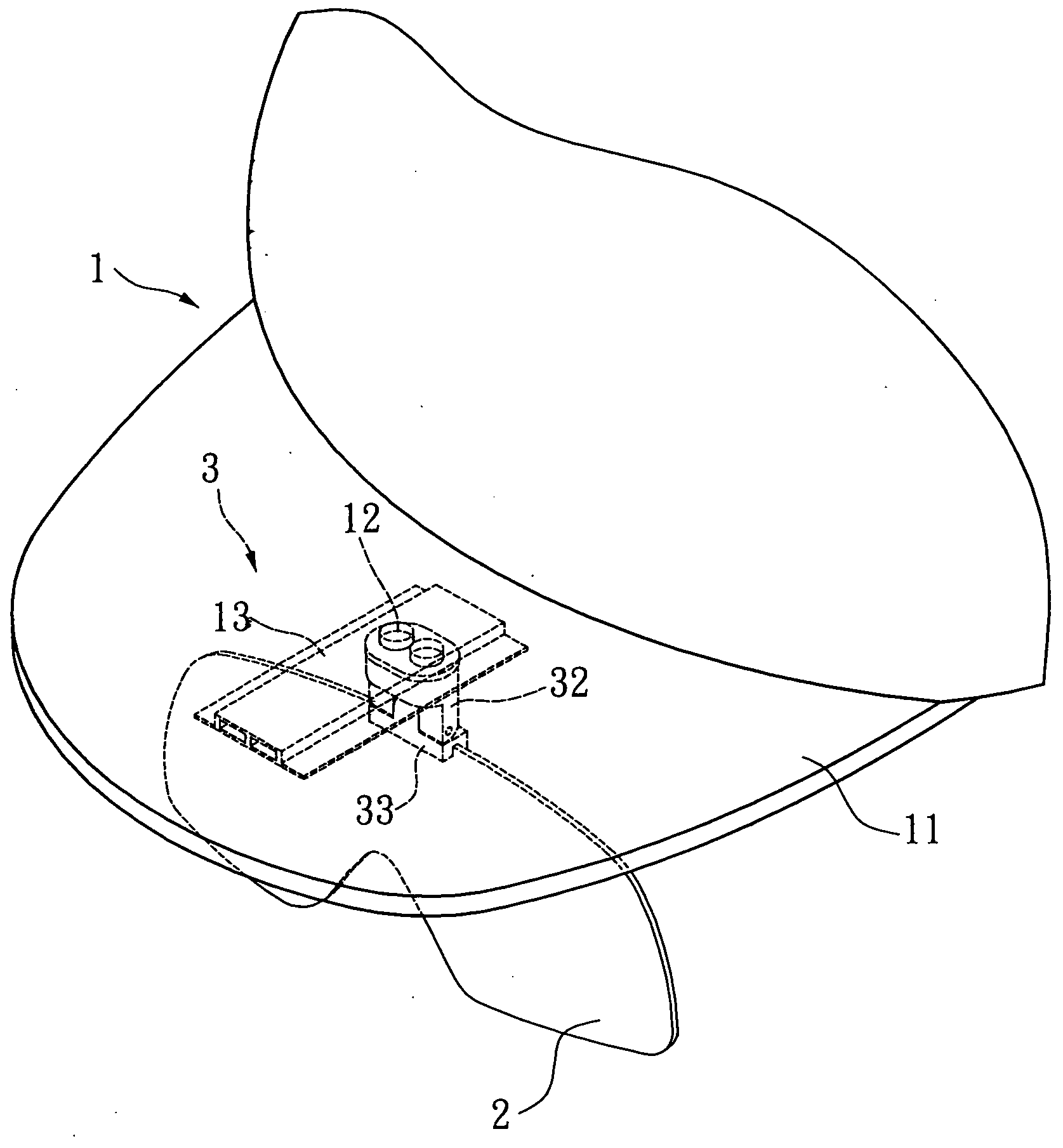
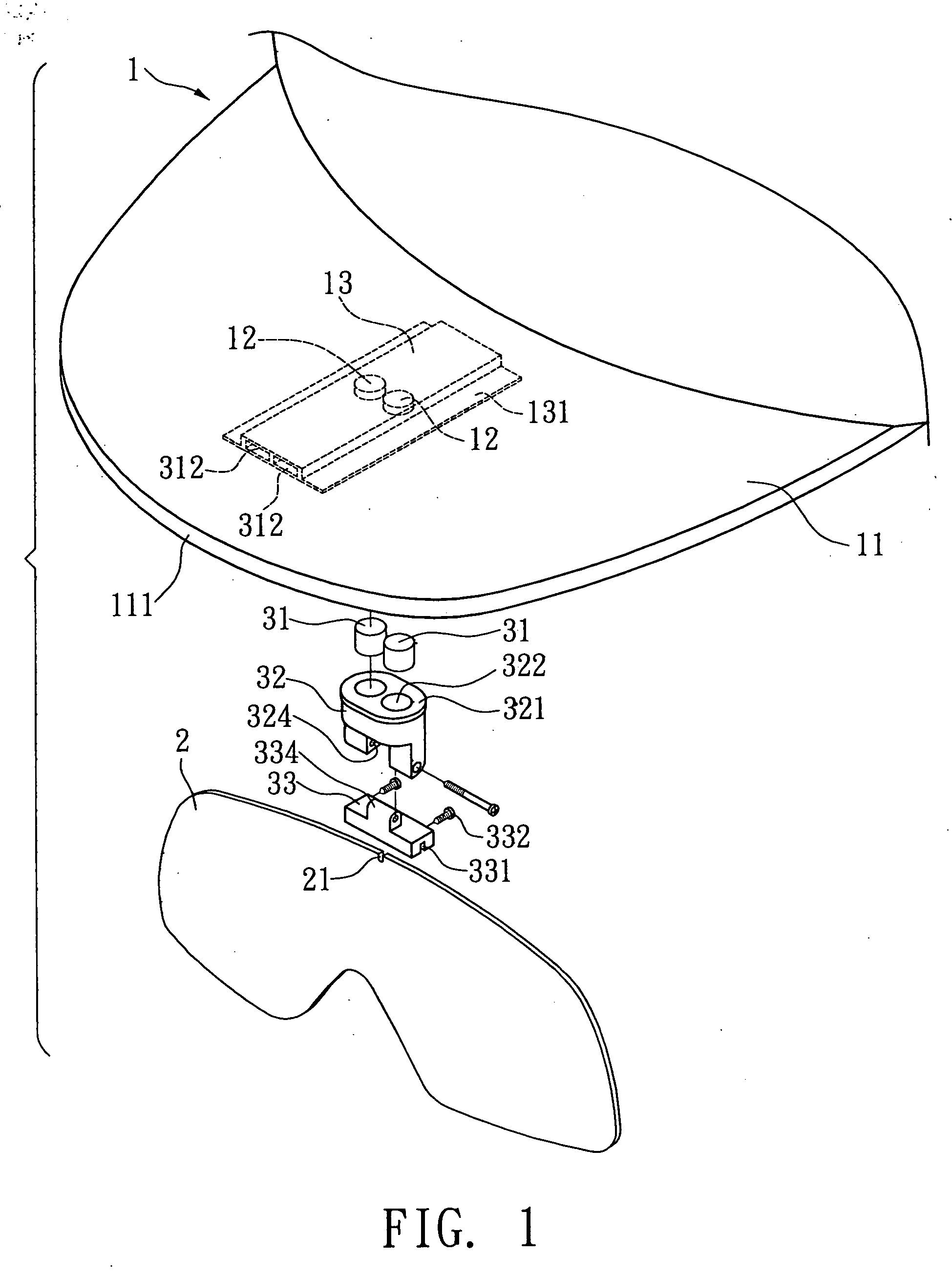
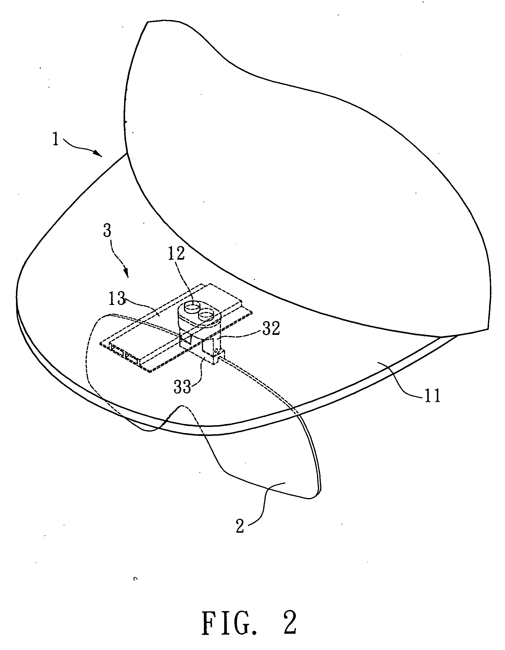
[0015] Please refer to FIGS. 1 and 2. The cap structure of the present invention includes a cap body 1, a glass 2 and a connecting unit 3 for connecting the cap body 1 with the glass 2.

[0016] The cap body 1 has a peak section 11 outward extending from a part of the periphery of the cap body 1. A magnetic member 12 is inlaid in the peak section 11. The magnetic member 12 is movable toward a front edge 111 of the peak section 11. In this embodiment, the magnetic member 12 is a circular magnet. An elongated rectangular seat body 13 is embedded in the peak section 11. The seat body 12 has two wing sections 131 on two sides for sewing the seat body 13 in the peak section 11. The seat body 13 is formed with two internal slide channels 312. Two magnetic members 12 are respectively placed in the slide channels 312 and reciprocally slidable within the slide channels 312.

[0017] The connecting unit 3 includes a pivot seat 32 and a pivot block 33 pivotally connected with the pivot seat 32. Tw...


PUM


Abstract

A cap structure including a cap body, a glass and a connecting unit for connecting the cap body with the glass. The cap body has a peak section outward extending from a part of the periphery of the cap body. At least one magnetic member is movably inlaid in the peak section. The connecting unit includes a pivot seat and a pivot block pivotally connected with the pivot seat. At least one magnetic member is disposed in one end of the pivot seat opposite to the pivot block, whereby the magnetic member of the peak section and the magnetic member of the pivot seat can attract each other. The glass is fixedly connected with one end of the pivot block opposite to the pivot seat.

Description

BACKGROUND OF THE INVENTION [0001] The present invention is related to a cap structure equipped with an adjustable glass. [0002]FIG. 7 shows a peak cap having a peak 81 equipped with a glass 9. A block body 91 rides on upper edge of the glass 9. A magnet 92 is inlaid in the block body 91. Another magnet 82 is disposed under the peak 81. The magnet 82 can attract the magnet 92 to assemble the glass 9 with the peak 81. When not used, the glass 9 can be detached from the peak 81. [0003] The magnet 82 is fixed under the peak 81 so that the position of the magnet 82 cannot be adjusted. Therefore, when the glass 9 is attracted by the magnet 82, the distance between the glass 9 and a user's eyes can be hardly adjusted as necessary. This leads to inconvenience in use of the peak cap. [0004] Moreover, when a user detaches the glass 9 from the peak 81, the user often incautiously misses the glass 9. SUMMARY OF THE INVENTION [0005] It is therefore a primary object of the present invention to p...

Claims


Application Information

Patent Timeline
Patent Type & Authority Applications(United States)
IPC IPC(8): A42B1/24
CPCA42B1/247G02C3/02G02C2200/02
Inventor FANG, CHIU-HSIUNG
Owner LIAO JUNG WEN
Why Eureka
Try Eureka