
Fishing lure

a technology of lures and lures, applied in the field of fishing lures, can solve the problems of limited simulation movement,

Inactive Publication Date: 2007-05-31
SEARCY JEREMY R
View PDF13 Cites 19 Cited by
  • Summary
  • Abstract
  • Description
  • Claims
  • Application Information

AI Technical Summary

Benefits of technology

[0014] Using the lure embodying the present invention will permit a fisherman to attract game fish by simulating the movements of a dying baitfish as the lure is pulled through the water by the fisherman. The dying baitfish is more likely to attract a target fish than a lure that merely simulates the swimming motion of a healthy baitfish and will still more attractive to a game fish than even a baitfish that is simply injured.

Problems solved by technology

Further, the simulated movement is usually limited to one particular type of movement.

Method used


Image

  • Fishing lure
  • Fishing lure

Examples


Embodiment Construction

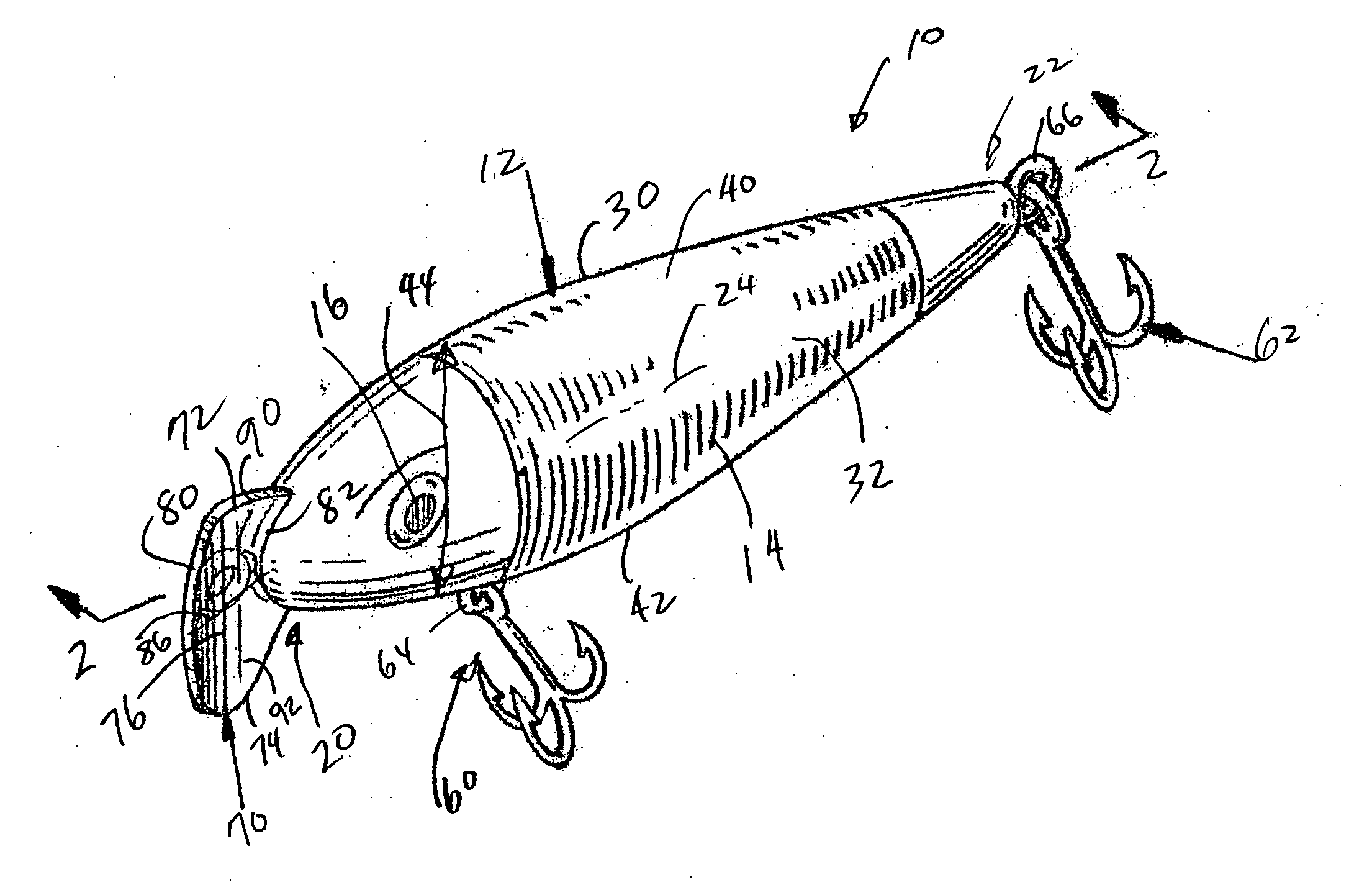
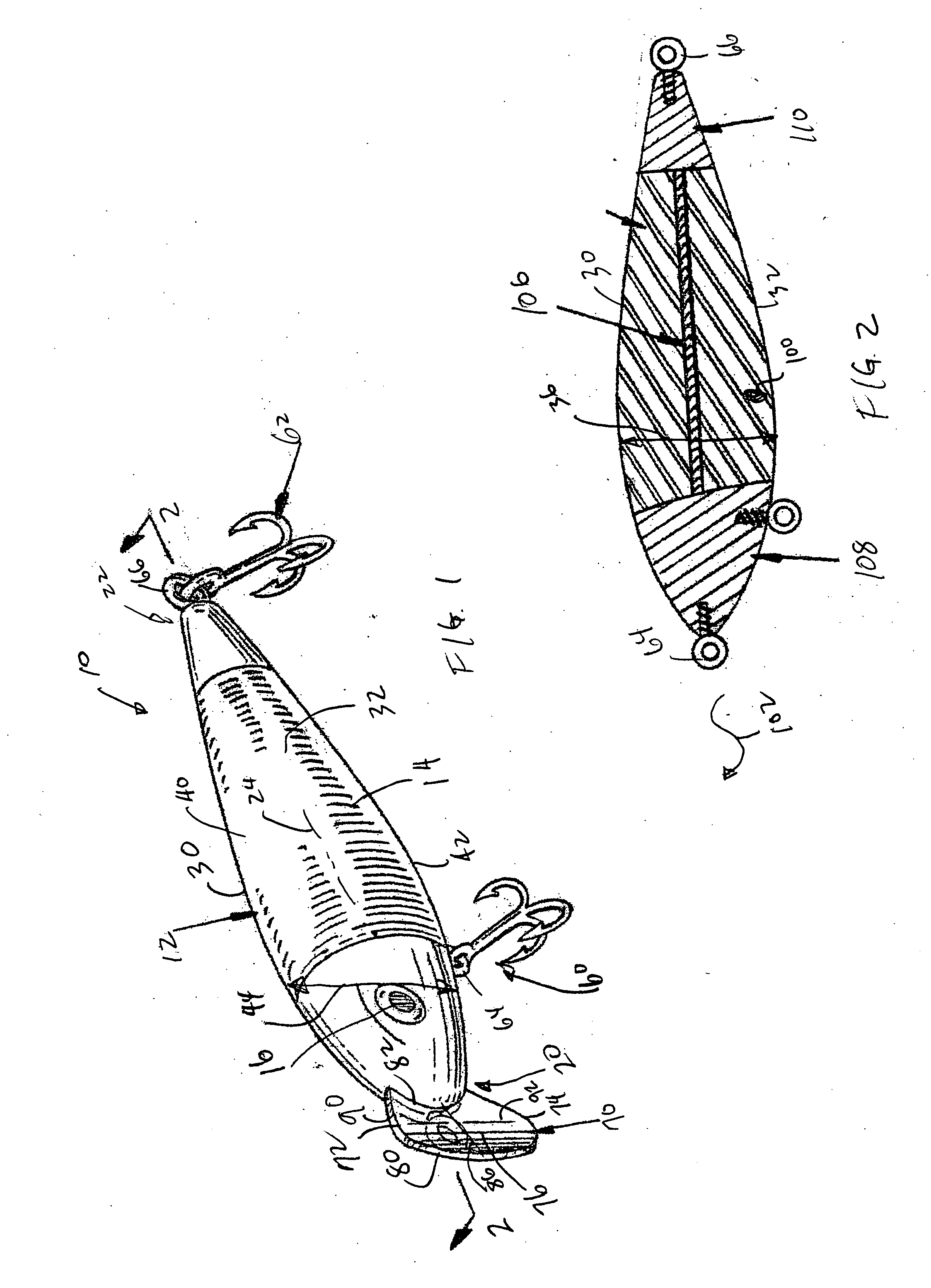
[0019] Referring to the figures, it can be understood that the present invention is embodied in a fishing lure 10 that simulates a dying minnow when pulled through water.

[0020] Lure 10 comprises a body 12 formed of soft flexible material, such as rubber or soft plastic and which can be decorated to appear like a minnow with scales 14, eyes 16 and the like. Lure 10 is adapted to move through water when pulled by a fisherman. Body 12 is able to assume either a dying-minnow orientation lying on its side or a swimming-minnow-orientation.

[0021] Body 12 has a first end 20 which is a forward end when the body is pulled through the water, a second end 22 which is an aft end when the body is pulled through the water and a longitudinal axis 24 which extends between first end 20 and second end 22. Body 12 further includes a first side 30 which is a top side when the body is oriented in the dying-minnow-orientation, a second side 32 which is a bottom side when the body is oriented in the dyin...


PUM


Abstract

A fishing lure that is in the form of a minnow and is weighted and designed to assume an orientation that appears to be a dying minnow as the lure is pulled through the water by a fisherman. The lure undulates on its side as it is pulled through the water.

Description

TECHNICAL FIELD OF THE INVENTION [0001] The present invention relates to the general art of fishing, and to the particular field of fishing lures. BACKGROUND OF THE INVENTION [0002] Fishing lures are typically attached to a fishing line and pulled through the water by a fisherman. Lures which simulate live bait have been used for many years and are available in various sizes and shapes. Many fishermen prefer lures instead of live bait for various reasons, including ease of handling and the economic advantages of not having to purchase or capture live bait. [0003] Fishing lures generally comprise essentially two components, namely some sort of fish-hooking component or mechanism and some sort of body member which serves the plural functions of carrying the fish-hooking component, providing a weight by which the fish-hooking component may be propelled, providing the connection between the fish-hooking component and the fishing line, and providing an appealing attraction which hopefull...

Claims


Application Information

Patent Timeline
IPC IPC(8): A01K85/00
CPCA01K85/00A01K85/16
Inventor SEARCY, JEREMY R.
Owner SEARCY JEREMY R
Learn More