Improved waveguide structure

a waveguide and waveguide technology, applied in the field of optical communication, can solve problems such as many techniques, and achieve the effect of eliminating strain effects and improving polarization crosstalk characteristics

Inactive Publication Date: 2007-05-31
LUCENT TECH INC
View PDF4 Cites 8 Cited by
  • Summary
  • Abstract
  • Description
  • Claims
  • Application Information

AI Technical Summary

Benefits of technology

[0003] I have developed, in accordance with the principles of the invention, optical waveguide structures that exhibit improved polarization crosstalk characteristics. More specifically, m...

Problems solved by technology

Unfortunately, such polarization crosstalk and polarization mode coupling defeats many of the techni...

Method used


Image

  • Improved waveguide structure
  • Improved waveguide structure
  • Improved waveguide structure

Examples


Embodiment Construction

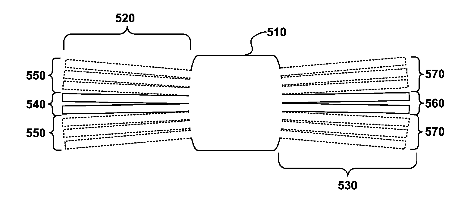
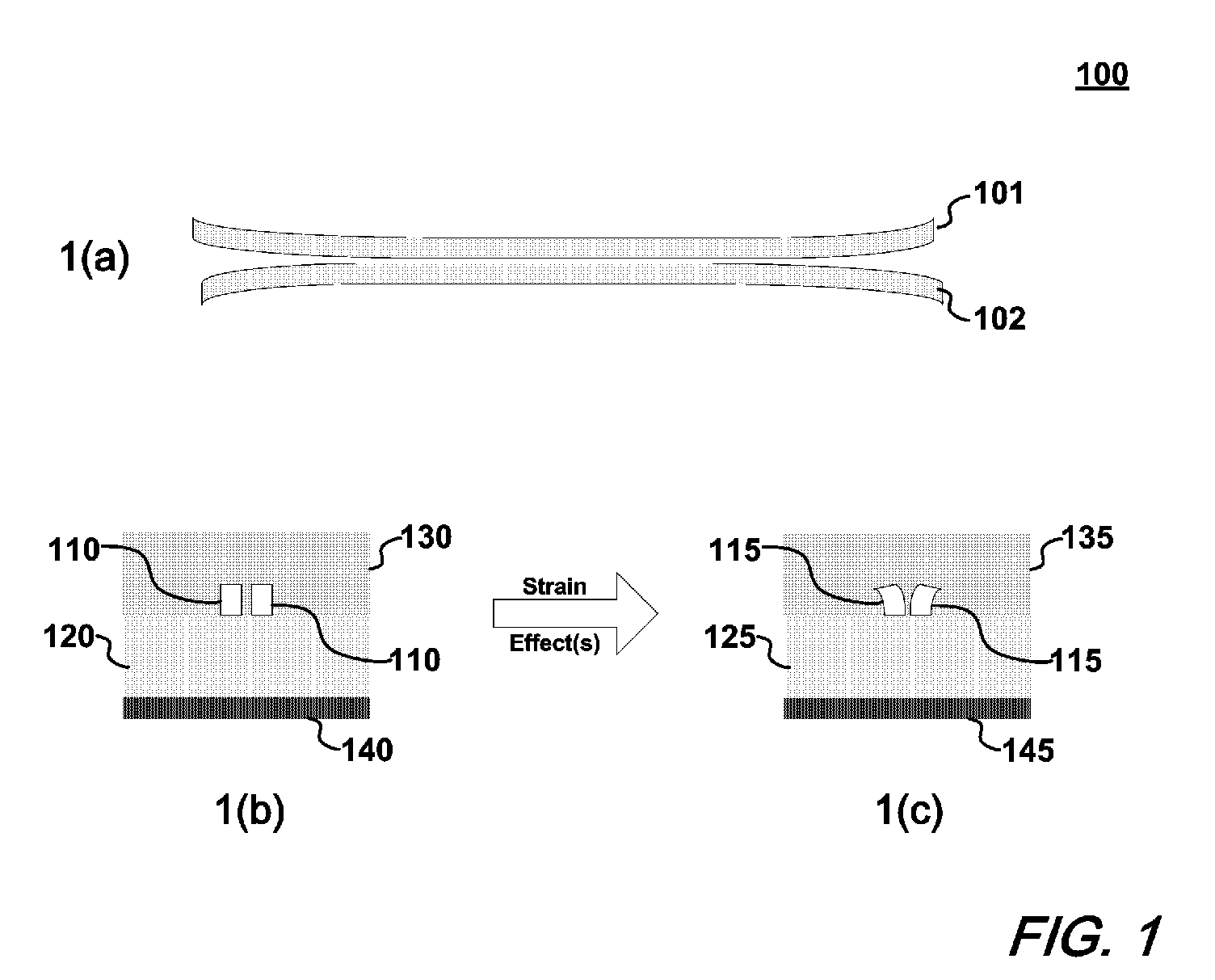
[0012]FIG. 1 shows a top-view and cross-sectional view(s) of a directional coupler and the effect(s) of strain on that coupler. More particularly, FIG. 1(a) shows a top-view of the directional coupler having multiple waveguide cores 101, 102. FIG. 1(b) shows a cross-sectional view of that same coupler without strain effects while FIG. 1(c) shows that same coupler with strain effects.

[0013] With initial reference to FIG. 1(b), there is shown the cross-sectional view of a directional coupler including a substrate 140 underlying a lower cladding material 120. Positioned on the lower cladding material 120 are waveguide cores 110. Overlying the waveguide cores 110 and lower cladding 120 is upper cladding material 130. As can be appreciated, the refractive indices of the waveguide cores 110, the lower cladding material 120, and upper cladding material 120, are chosen such that a desired internal reflection of optical signals traversing the waveguide cores 110 is achieved.

[0014] When opt...


PUM


Abstract

An improved waveguide structure employing blocks of waveguide core material positioned sufficiently close to a waveguide core thereby eliminating strain effects and its resulting undesirable polarization crosstalk. The improved structures are applicable to a variety of optical components including bent waveguides, directional and star couplers.

Description

FIELD OF THE INVENTION [0001] This invention relates generally to the field optical communications and in particular to waveguide design(s) that reduce stress-induced polarization crosstalk. BACKGROUND OF THE INVENTION [0002] Silica waveguide, Planar Lightwave Circuits (PLCs) ideally exhibit polarization modes that are independent from one another. However, certain lightwave components such as directional couplers, exhibit polarization crosstalk—a phenomenon in which the polarization modes are coupled. Unfortunately, such polarization crosstalk and polarization mode coupling defeats many of the techniques that are used to achieve polarization independence—a necessary characteristic of many optical devices. SUMMARY OF THE INVENTION [0003] I have developed, in accordance with the principles of the invention, optical waveguide structures that exhibit improved polarization crosstalk characteristics. More specifically, my inventive structures employ additional waveguide core material—pla...

Claims


Application Information

Patent Timeline
IPC IPC(8): G02B6/26G02B6/42G02B6/10
CPCG02B6/125G02B6/13G02B6/2848
Inventor DOERR, CHRISTOPHERR
Owner LUCENT TECH INC
Why Eureka
Try Eureka