Optical code division multiplexing transmission/reception method and optical code division multiplexing transmission/reception device

a transmission/reception device and optical code technology, applied in the field of optical communication devices, can solve the problems of beat noise, cross-correlated waveform components cannot be completely eliminated, etc., and achieve the effect of minimising beat nois

Inactive Publication Date: 2007-05-31
OKI ELECTRIC IND CO LTD
View PDF2 Cites 33 Cited by
  • Summary
  • Abstract
  • Description
  • Claims
  • Application Information

AI Technical Summary

Benefits of technology

[0099] Hence according to the first invention, interference between chip pulses does not occur, so that even when the number of multiplexed channels is large, or when the code period is set to be short, decoded optical pulse signals in which cross-correlated waveform components are sufficiently eliminated are obtained, and there is the advantage that received signals can be obtained with minimal beat noise occurring due to the superpositioning of the edge portions on the frequency axis of chip pulses forming auto-correlated waveforms and chip pulses forming cross-correlated waveforms.
[0103] Hence according to the second invention, by comprising a first polarization control step and a second polarization control step, in addition to the advantage that, even when the number of channels multiplexed is large, or when the code period is set to be short, there is minimal beat noise caused by the superpositioning of the edge portions on the frequency axis of chip pulses forming auto-correlated waveforms and of chip pulses forming cross-correlated waveforms, similarly to the optical code division multiplexing transmission / reception method of the first invention, there is also the advantage that decoded optical pulse signals can be obtained having minimal beat noise caused by the superpositioning of adjacent wavelength components on the frequency axis of auto-correlated waveforms as well.

Problems solved by technology

However, when using an optical code division multiplexing transmission / reception method employing conventional time-spreading wavelength-hopping codes comprising the above-described time gate processing means, when the degree of multiplexing (the number of channels multiplexed) is high, and when the code period Tc is set to be short, cross-correlated waveform components appear at positions close to the auto-correlated waveforms on the time axis, so that there are cases in which the cross-correlated waveform components cannot be completely eliminated even when time gate processing means is executed.
That is, in conventional methods the edges on the frequency axis of chip pulses forming cross-correlated waveforms are superposed on each other, and as a result cause beat noise to occur.

Method used


Image

  • Optical code division multiplexing transmission/reception method and optical code division multiplexing transmission/reception device
  • Optical code division multiplexing transmission/reception method and optical code division multiplexing transmission/reception device
  • Optical code division multiplexing transmission/reception method and optical code division multiplexing transmission/reception device

Examples


first embodiment

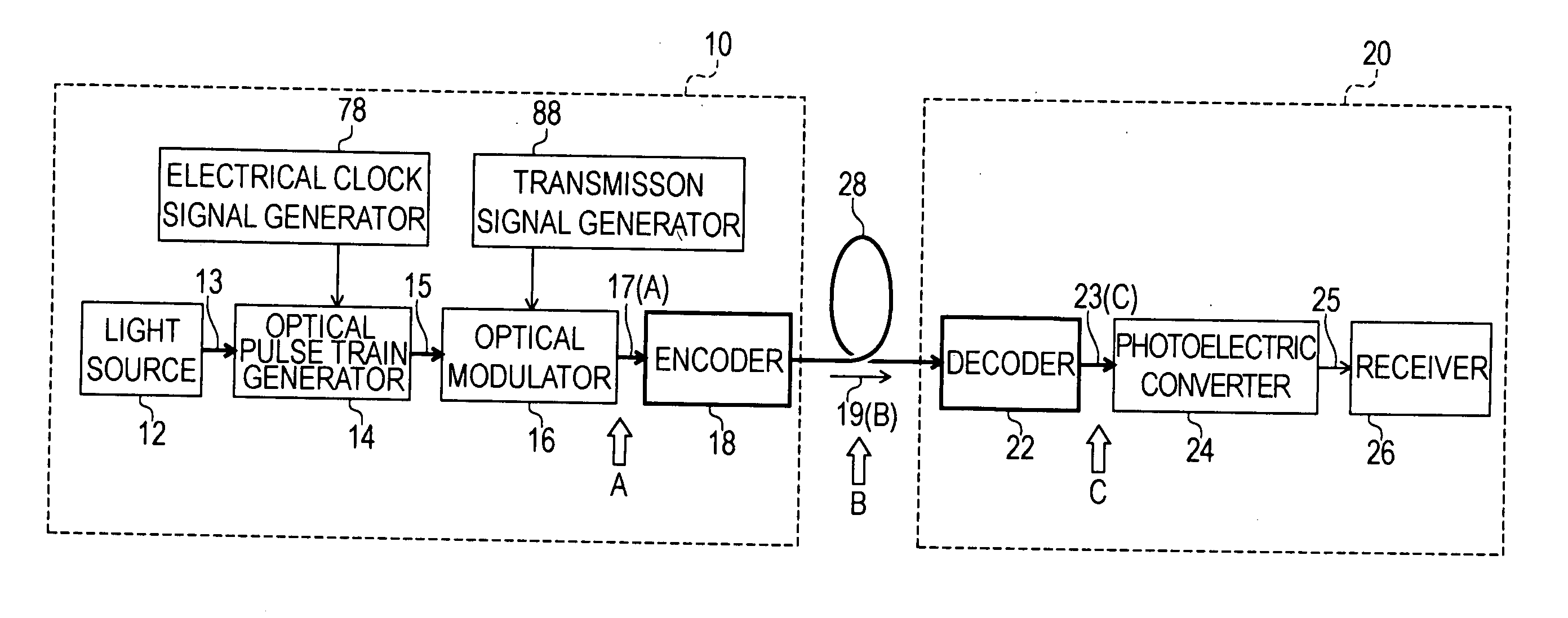
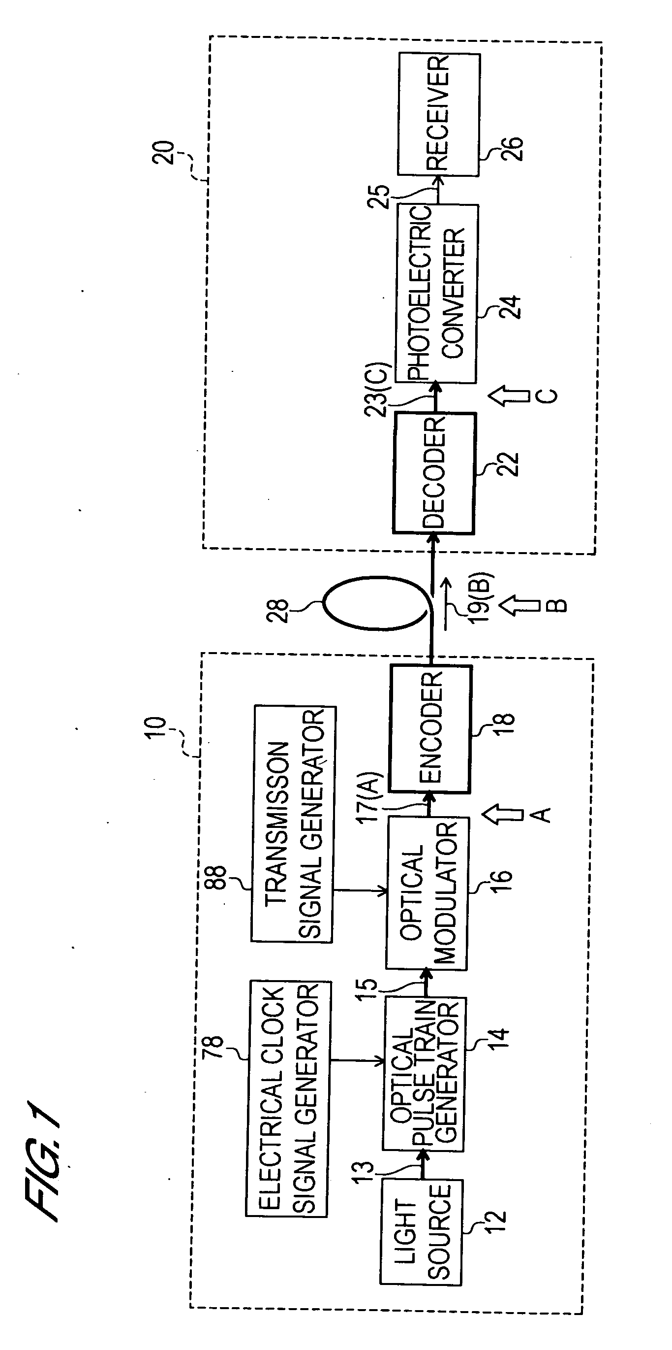
[0120] The optical code division multiplexing transmission / reception method of a first invention, and the structure and operation of a device to implement this method, are explained referring to FIG. 8 and FIG. 9. FIG. 8 is a summary block diagram of the transmission unit of a device to implement the optical code division multiplexing transmission / reception method of the first invention. FIG. 9 is a summary block diagram of the reception unit of a device to implement the optical code division multiplexing transmission / reception method of the first invention, or of a second invention, described below. In FIG. 8 and FIG. 9, a case is shown in which the number of channels multiplexed is four; however, the following explanation is clearly not limited to the case of four channels, but obtains similarly for other numbers of channels.

[0121] As shown in FIG. 8, the transmission unit 100 comprises an optical pulse train generation unit 102, optical splitter 116, first channel encoded optica...

second embodiment

[0158] The optical code division multiplexing transmission / reception method of a second invention, and the structure and operation of a device to implement this method, are explained referring to FIG. 11 and FIG. 9. FIG. 11 is a summary block diagram of the transmission unit of a device to implement the optical code division multiplexing transmission / reception method of the second invention; FIG. 9 is a summary block diagram of the reception unit. In FIG. 11 and FIG. 9, a case is shown in which the number of channels multiplexed is four; but the following explanation is clearly not limited to a case of four channels, but applies to other cases as well.

[0159] As shown in FIG. 11, the transmission unit 200 comprises an optical pulse train generation unit 202, optical splitter 216, first channel encoded optical pulse signal generation unit 218, second channel encoded optical pulse signal generation unit 220, third channel encoded optical pulse signal generation unit 224, fourth channe...


PUM


Abstract

A transmission unit comprises an optical pulse train generation unit, first channel encoded optical pulse signal generation unit, second channel encoded optical pulse signal generation unit, third channel encoded optical pulse signal generation unit, and fourth channel encoded optical pulse signal generation unit; the second and fourth channels further comprise polarization controllers respectively. By means of these polarization controllers, a polarization control step is executed in which the planes of polarization of first encoded optical pulse signals of the second and fourth channels are rotated by 90°. By executing the polarization control step, the directions of the planes of polarization of the first decoded optical pulse signals of adjacent channels in the reception unit can be caused to be mutually orthogonal.

Description

BACKGROUND OF THE INVENTION [0001] 1. Field of the Invention [0002] The present invention relates to an optical communication device, and in particular relates to means to reduce reception error rates in an optical code division multiplexing (OCDM) transmission / reception device. [0003] 2. Description of Related Art [0004] In metropolitan areas which are positioned midway between long-distance networks (which may also be called the “Internet backbone”) and access lines, there is a mounting need for communication at faster communication speeds and with larger data capacity. This is because, whereas the bitrate of the existing Internet backbone is secured in the terabit-per-second communication range, in metropolitan areas communication speeds and capacities lag behind. Hereafter, in consideration of such circumstances as the spread of Internet use and increasing broadband content transmission, faster and higher-capacity communication in metropolitan areas is desired. [0005] In order t...

Claims


Application Information

Patent Timeline
Patent Type & Authority Applications(United States)
IPC IPC(8): H04J14/00H04B1/713H04B10/2507H04J14/04H04J14/06
CPCH04J14/005H04J14/02H04J14/06
Inventor TAMAI, HIDEAKI
Owner OKI ELECTRIC IND CO LTD
Why Eureka
Try Eureka