Natural gas treatment process for stimulated well

a well stimulation and treatment process technology, applied in the separation process, auxillary pretreatment, borehole/well accessories, etc., can solve the problems of unsuitable gas to be sent to its original destination, environmental damage, and clearly not practicable to apply cryogenic technology for such a short-term us

Inactive Publication Date: 2007-06-07
MEMBRANE TECH & RES
View PDF9 Cites 75 Cited by
  • Summary
  • Abstract
  • Description
  • Claims
  • Application Information

AI Technical Summary

Benefits of technology

[0012] The invention is a process for treating natural gas produced by a recently stimulated well to reduce the concentration of fracturing gas in the natural gas to a desired level.

Problems solved by technology

Until the fracturing gas content drops, the gas is usually unsuitable to be sent to its original destination, typically a gas pipeline or gas processing facility.
Absent any technically or economically feasible treatment technology, the stimulant-rich gas is simply vented or flared, options that waste otherwise valuable natural gas that is coproduced during this period and are environmentally harmful.
Unless the well happens to be adjacent to a gas processing plant with cryogenic distillation capabilities, it is clearly not practical to apply cryogenic technology for such a short-term use.
In addition, the rapidly changing nitrogen content of the gas would make the use of cryogenics very difficult.
Even a membrane system will have difficulties treating post-stimulation gas, however, because the performance of the membrane unit varies with the feed gas composition, feed flow rate and gas pressure.
In the case of a gas stream produced by a well after stimulation, the difficulty is exacerbated because the concentration of fracturing gas changes by the hour, especially in the first days after stimulation.
A system designed to treat the initial gas composition will significantly overprocess the gas as time goes on, wasting energy to do so.
The product streams may also fail to meet the target specifications for their pre-stimulation destinations.
Likewise, a system designed for a certain flow rate or feed pressure will not be able to maintain consistent performance if the flow or pressure of the feed gas increases or decreases.

Method used


Image

  • Natural gas treatment process for stimulated well
  • Natural gas treatment process for stimulated well
  • Natural gas treatment process for stimulated well

Examples


example 1

Embodiment of FIG. 2

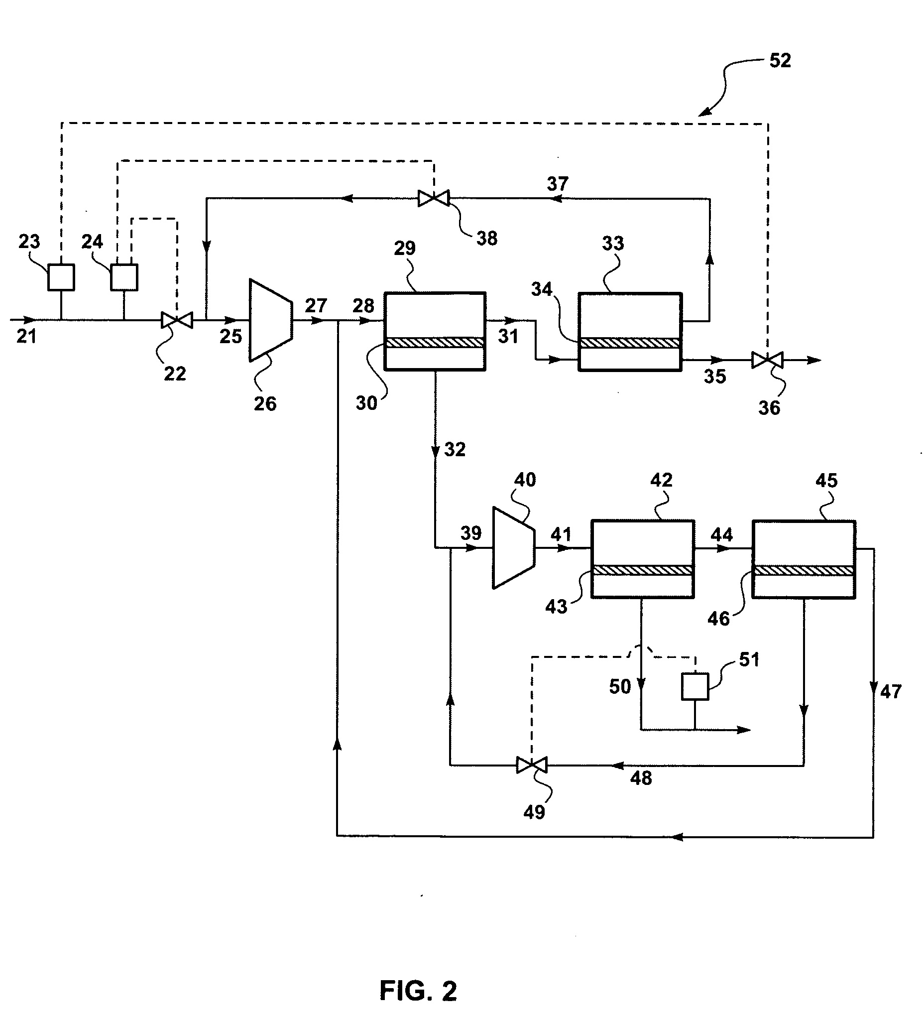
[0161] Computer calculations were performed with a modeling program, ChemCad 5.5 (ChemStations, Inc., Houston, Tex.), to illustrate the process of the invention for removal of nitrogen after stimulation of a natural gas well. The process was assumed to be carried out as shown in FIG. 2.

[0162] To model the behavior of a process control system varying process parameters in response to changing feed gas properties, a series of calculations was performed for natural gas containing a fracturing gas content varying from 31 vol % nitrogen to 12 vol % nitrogen. The target was to reduce the nitrogen content in the product stream to about 10 vol % under all conditions, so that the gas could be pooled with gas from other wells that are in regular production mode.

[0163] Secondary targets were to achieve high levels of gas recovery into the product stream, and to control the amount of compressor horsepower used by the process.

Calculation 1: Raw gas composition: 31 vol % n...

example 2

Variable Membrane Area: Embodiment of FIG. 3

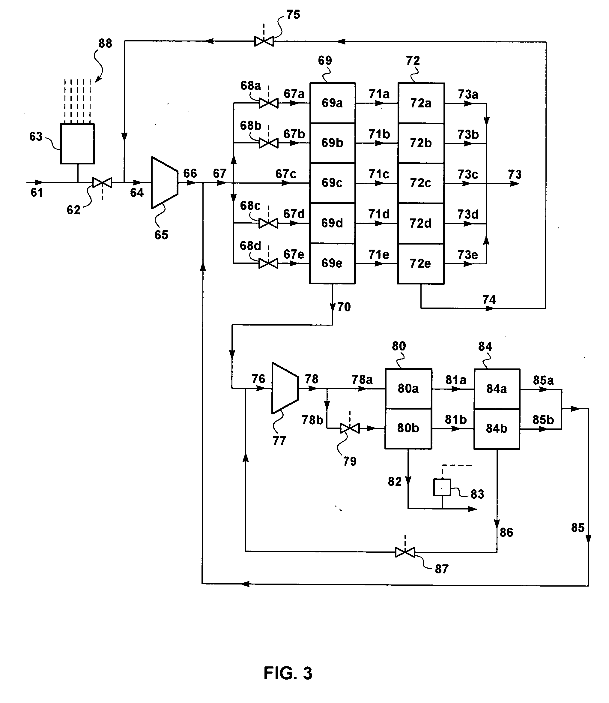
[0179] Computer calculations were performed with ChemCad 5.5 to illustrate the process of the invention shown in FIG. 3. It was assumed that the first stage membrane banks, 69 and 72, each contain 5 tubes of membrane modules, exactly as shown in the figure, but that the second stage membrane banks, 80 and 84, each contain 7 tubes of membrane modules. It was assumed that a valve is provided at the inlet to every tube of the first steps, 69 and 80, of both stages, so that the number of tubes-on-stream can be varied from 0 to 12.

[0180] As with Example 1, series of calculations was performed for natural gas containing a fracturing gas content varying from 31 vol % nitrogen to 12 vol % nitrogen. The target was again to reduce the nitrogen content in the product stream to about 10 vol %, as well as to achieve high levels of gas recovery and control compressor horsepower used.

Calculation 1: Inlet gas composition: 31% nitrogen. Feed gas flow ra...

case 2

gas composition: 20% nitrogen. Feed gas flow rate: 2.8 MMscfd.

[0183] The calculation was repeated assuming that the nitrogen content of the feed gas has dropped to 20 vol % and the feed gas flow rate has dropped to 2.8 MMscfd.

[0184] The membrane area was assumed to be reduced by closing two of the valves to the first steps of the first membrane stage, and one of the valves to the first steps of the second membrane stage. Valves 75 and 87 were assumed to be adjusted by the process control system, so that the recycle flow of streams 74 and 85 is reduced. As this embodiment does not have a pressure regulating valve on the residue discharge line, the feed pressure for both membrane stages remains at about 500 psia.

[0185] The results of the calculation are shown in Table 6.

TABLE 6Stream61666774737076858682Flow (MMscfd)2.83.34.90.50.53.96.41.62.52.3Temp (° F.)120120112858010110296104116Pressure (psia)305515503115466115115503115103Component (vol %)Nitrogen2024284268211837159.8Methane78...


PUM

PropertyMeasurementUnit
vol %aaaaaaaaaa
timeaaaaaaaaaa
vol %aaaaaaaaaa

Abstract

A process and equipment for treating natural gas produced by a well that has recently been stimulated, and that contains an undesirably high concentration of the fracturing gas used to stimulate the well. The process involves treating the gas by membrane separation, and provides for control of treatment parameters to compensate for the changing concentration of fracturing gas in the produced gas, as well as changes in gas flow rate.

Description

FIELD OF THE INVENTION [0001] The invention relates to processes and equipment for removing a fracturing gas, such as nitrogen, from natural gas. BACKGROUND OF THE INVENTION [0002] Hydraulic fracturing is used to create cracks in oil- or gas-bearing formations to facilitate movement of oil or gas to a well bore and stimulate production from that well. [0003] Fracturing is performed by pumping a fluid at high pressure down the well and into the formation. The fluid may be water, carbon dioxide or nitrogen, for example. The fluid usually contains sand or other “proppant” to hold the fracture open after the fracturing fluid has dissipated or been pumped out, as well as viscosity modifiers and other optional components. [0004] Immediately after a gas well has been stimulated, for example using nitrogen as the fracturing fluid, the nitrogen content of the gas emerging from the well is extremely high. After a short time, typically no more than a week or ten days, the gas returns to its pr...

Claims


Application Information

Patent Timeline
Patent Type & Authority Applications(United States)
IPC IPC(8): E21B33/16E21B37/00E21B43/25
CPCB01D53/22C10L3/10C10L3/102B01D53/226B01D53/227B01D53/30B01D2257/102B01D2257/504Y02C10/10Y02C20/40
Inventor LOKHANDWALA, KAAEID A.JARIWALA, ANKUR
Owner MEMBRANE TECH & RES
Why Eureka
Try Eureka