Wiper control method and wiper control device

Inactive Publication Date: 2007-06-14
NILES PARTS CO LTD
View PDF12 Cites 1 Cited by
  • Summary
  • Abstract
  • Description
  • Claims
  • Application Information

AI Technical Summary

Benefits of technology

[0013] The present invention provides a wiper control method and a wiper control device which can smoothly respond to change of rainfall situation and more particularly a wiper control method and a wiper control device which can smoothly respond to rapid change of rainfall situation when passing through a rainfall shutoff environment such as in a tunnel.
[0014] Also, the present invention is based on a new finding that the above assumption of the size of water wall=rainfall is not necessarily correct all the time. And the present invention provides a wiper control method and a wiper control device which can appropriately follow change of the rainfall situation and more particularly to a wiper control method and a wiper control device which can appropriately follow the change of rainfall situation if an adhesion amount of rainfall onto a windshield is rapidly changed such as entrance to / exit from a tunnel.

Problems solved by technology

However, this assumption of the size of water wall=rainfall is not applicable to all the driving scenes.
Also, a considerable amount of water is supplied to the windshield by the above dripping water.
In general, continuous operation of a wiper not in the rainfall situation to some extent is felt as extremely bothersome.
WO 91 / 03393, control of intermittence is affected by the rainfall state immediately before even if the rainfall has stopped, and the situation that the continuous operation lasts and is felt bothersome may happen easily, which is a problem.

Method used


Image

  • Wiper control method and wiper control device
  • Wiper control method and wiper control device
  • Wiper control method and wiper control device

Examples


second preferred embodiment

[0154] Next, a second preferred embodiment of the present invention will be described. The above-mentioned first preferred embodiment adjusts correspondence between the rainfall level and the wiping level, while the second preferred embodiment of the present invention adjusts detection sensitivity of raindrops.

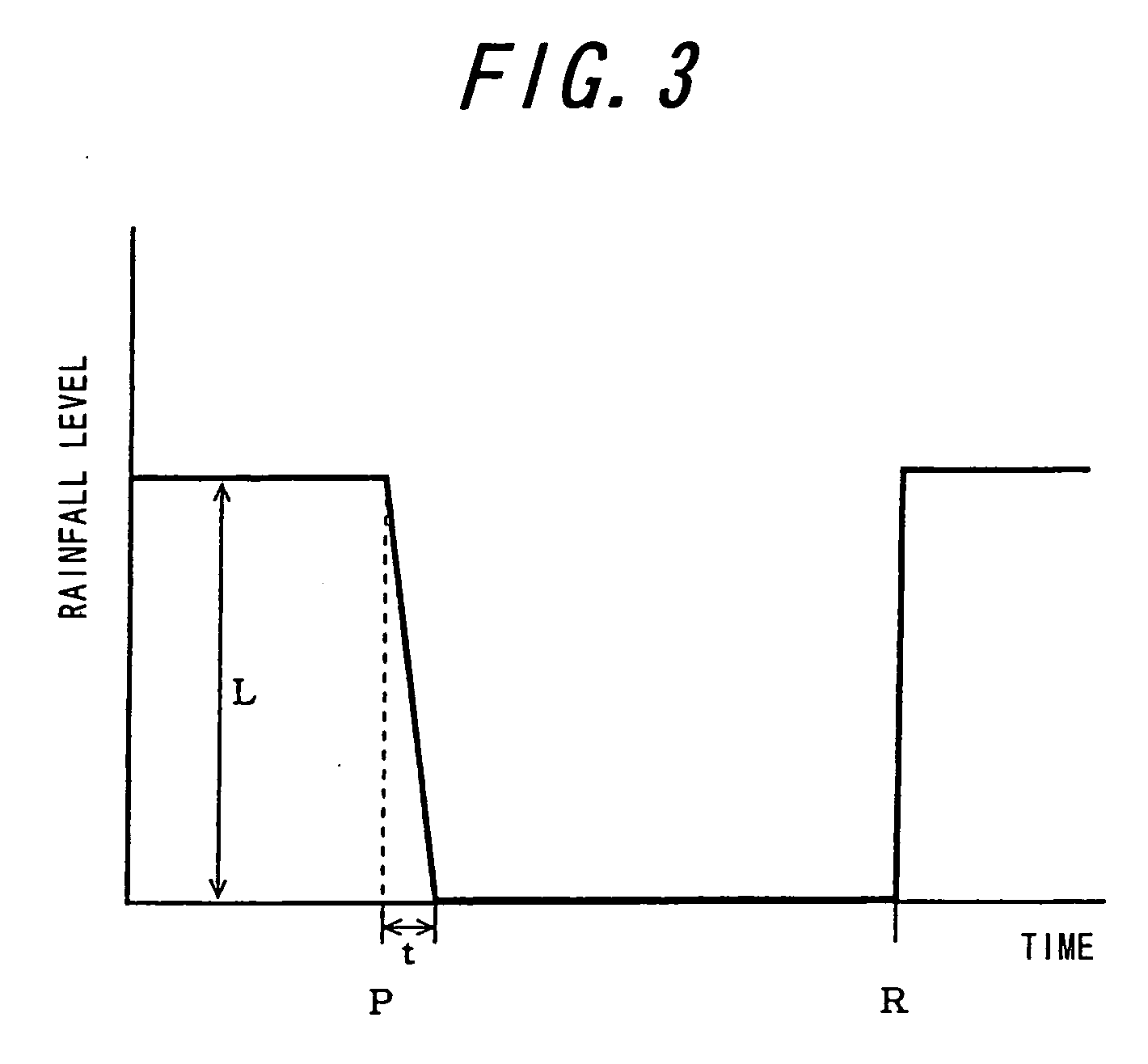
[0155] First, in a rainfall situation with rainfall more than predetermined, a waveform of an output signal of a light receiving element when a vehicle running at a high speed of about 100 km / h exits from a tunnel will be described. FIG. 12 is a diagram for explaining the waveform model of the output signal of the light receiving element and shows a model of the signal waveform when the wiper performs the first wiping after exit from the tunnel.

[0156] In FIG. 12, when adhesion of raindrops after exit from the tunnel is detected, the wiper is driven to perform the first wiping. By this first wiping, the raindrops adhering on the detection surface are eliminated and the signal...

third preferred embodiment

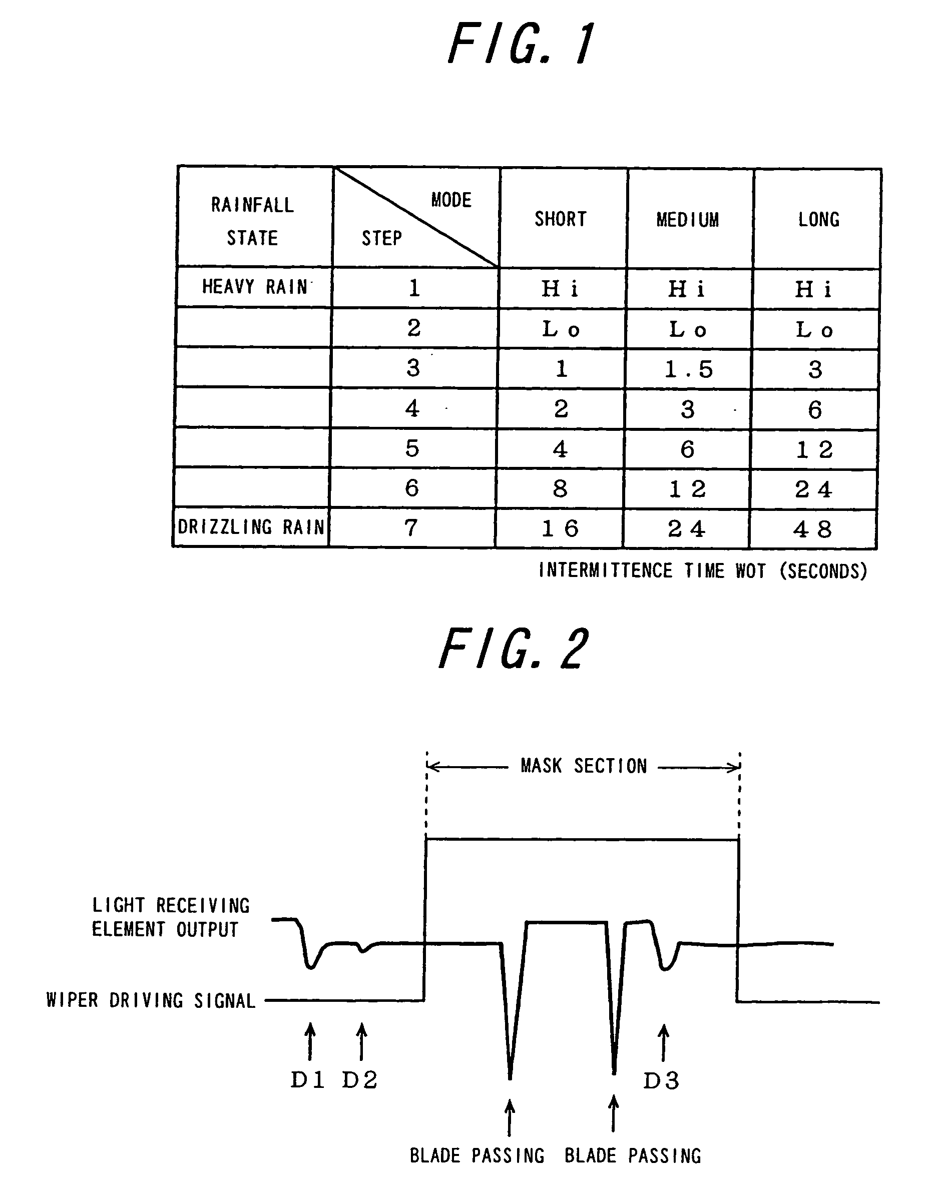
[0167] Next, a third preferred embodiment of the present invention will be described. FIG. 14 is a diagram for explaining operation of the wiper when the wiper blade passes through the detection surface. FIG. 15 is a diagram showing a waveform model of the output signal of the light receiving element when the wiper blade passes through the detection surface in the case of no adhesion of raindrops. As shown in FIG. 14, the wiper blade passes through the detection surface by outgoing motion, reverses after passing through the detection surface, starts return motion, passes through the detection surface and returns to the original position.

[0168] Next, the waveform model of FIG. 15 will be described. In FIG. 15, the waveform in the mask section is divided into some sections according operation of the wiper. That is, they are a signal A till the wiper blade passes through the detection surface on the outgoing path, a signal X1 when passing through the detection surface on the outgoing ...

fourth preferred embodiment

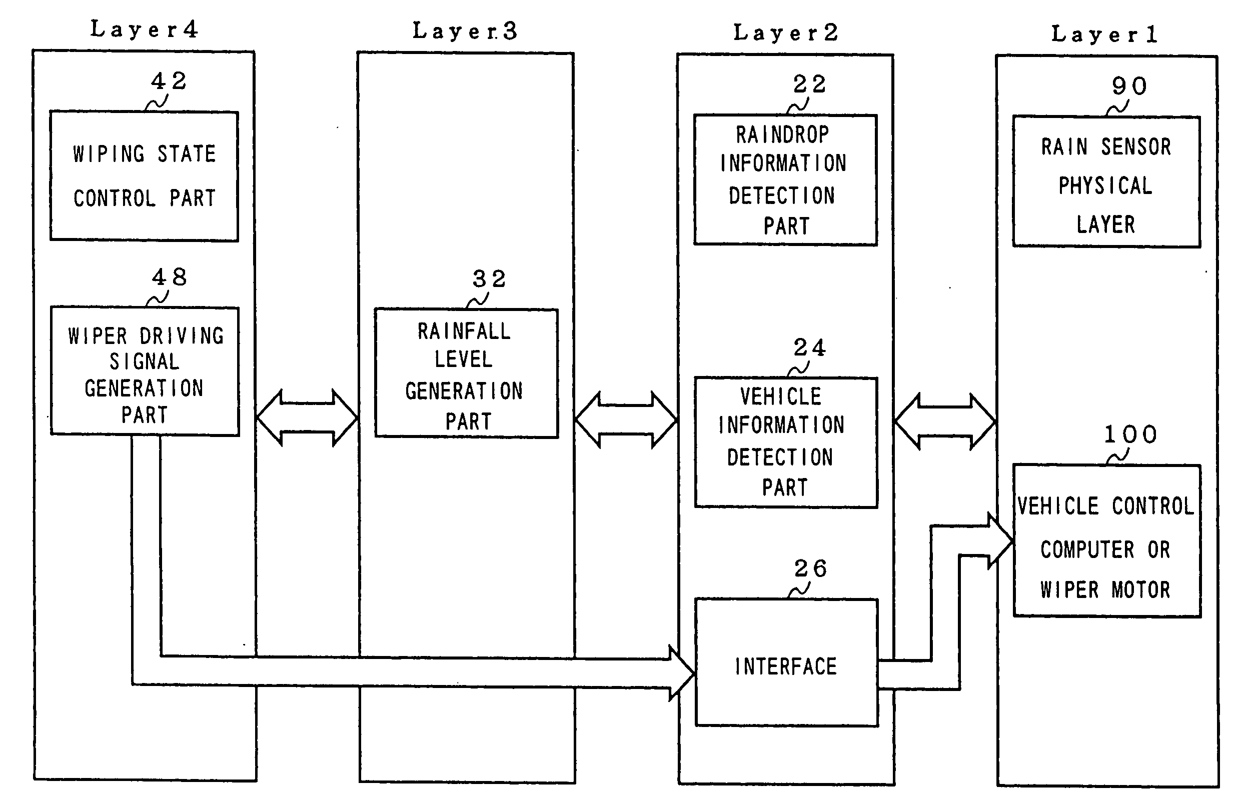
[0182] The configuration of a wiper control device according to the fourth preferred embodiment of the present invention will be described referring to FIG. 20. FIG. 20 is a block diagram for explaining the configuration of the wiper control device according to the fourth preferred embodiment of the present invention in the layered structure. In FIG. 20, the wiper control device according to the fourth preferred embodiment of the present invention can be represented by three-layered construction, and between each of the layers, data or signals are made to communicate through a common interface such as SAP (service access point), for example. A first layer includes a rain sensor physical layer 190 and a vehicle control computer or a wiper motor 1100, a second layer includes a raindrop detection part 122, a detection part 124 for a water amount collected by a wiper and an interface 126, a third layer includes a wiping state control part 132 and a wiper stop control part 134. Each of t...


PUM


Abstract

A wiper control method and a wiper control device are provided which can smoothly respond to rapid change of a rainfall situation at passage of a rainfall shutoff environment such as a tunnel. A wiping state control part 42 determines entry of a vehicle into the rainfall shutoff environment, sets a wiping level low for the low level of rainfall less than a predetermined rainfall level in response to this determination or sets the wiping level high for the high level rainfall at the predetermined rainfall level or more. A rainfall level generation part 32 detects adhesion of raindrops and determines the rainfall level. A wiper driving signal generation part 48 determines wiper operation based on the rainfall level determined by the rainfall level generation part 32 and the wiping level set by the wiping state control part 42.

Description

FIELD OF THE INVENTION [0001] The present invention relates to a wiper control method and a wiper control device which can smoothly respond to change of rainfall situation and more particularly to a wiper control method and a wiper control device which can smoothly respond to rapid change of rainfall situation when passing through a rainfall shutoff environment such as in a tunnel. [0002] Also, the present invention relates to a wiper control method and a wiper control device which can appropriately follow change of the rainfall situation and more particularly to a wiper control method and a wiper control device which can appropriately follow the change of rainfall situation if an adhesion amount of rainfall onto a windshield is rapidly changed such as entrance to / exit from a tunnel. BACKGROUND ART [0003] A conventional device for controlling a wiper by injecting an LED light or the like onto a detection surface provided on a windshield and by receiving a reflected light by a light ...

Claims


Application Information

Patent Timeline
IPC IPC(8): H02P1/04B60S1/08
CPCB60S1/0818B60S1/08G01N21/17G01W1/14
Inventor KOKURYO, KAZUTOMAKINO, YOSHITERUFURUSAWA, SATOSHI
Owner NILES PARTS CO LTD
Why Eureka
Try Eureka