Electrical connector with terminals joining board terminals

a technology of electrical connectors and terminals, applied in the direction of securing/insulating coupling contact members, coupling device connections, printed circuits, etc., can solve the problem of difficulty in making the conventional joining electrical connectors with a lower profile, and achieve the effect of reducing the profile of the joining terminal and less resistan

Inactive Publication Date: 2012-07-24
HIROSE ELECTRIC GROUP
View PDF8 Cites 1 Cited by
  • Summary
  • Abstract
  • Description
  • Claims
  • Application Information

AI Technical Summary

Benefits of technology

[0013]According to the aspect of the present invention, the supported section is provided to have at least a part thereof in the connector fitting direction overlapped with a range of the main body section in the direction. Therefore, it is possible to reduce a size of the joining electrical terminal in the connector fitting direction for an amount of the overlap and thereby it is possible to attain a lower profile of the joining electrical connector.
[0014]According to the aspect of the present invention, each supported section of the joining terminals may be formed so as to protrude in the connector fitting direction, and supported while contacting with the housing in the connector fitting direction. Since the supported section is supported in a state that is almost a point contact by the housing, the support area is small, so that the friction between the supported section and the housing is small. Therefore, when the joining terminal moves in the terminal arrangement direction responding to the displacement in the relative positions of the board electrical connectors, it is possible to smoothly respond to the displacement of the board electrical connectors.
[0018]As describe above, the first support member and the second support member can move relative to each other in the terminal arrangement direction within the range of the gap. Accordingly, the main body section and the supported section of each joining terminal can move responding to the displacement of the board electrical connectors. Furthermore, according to the invention, the first support member and the second support member can move relative to each other. Accordingly, there is no elastic deformation generated between the first support member and the second support member. Therefore, there is no reaction force due to the elastic deformation, and the main body section and the supported section of the joining terminal can move with less resistance.
[0019]As described above, according to the invention, the supported section of the joining terminal is provided to have at least a part thereof overlapped within the range of the main body section in the connector fitting direction. Accordingly, it is possible to reduce the profile of the joining terminal and in turn the profile of the joining electrical connector in the connector fitting direction.

Problems solved by technology

Accordingly, the dimension of the joining terminal in the up-and-down direction (height dimension) is not smaller than a total height of the legs and the joining section, so that it is difficult to make the conventional joining electrical connector with a lower profile.

Method used


Image

  • Electrical connector with terminals joining board terminals
  • Electrical connector with terminals joining board terminals
  • Electrical connector with terminals joining board terminals

Examples


first embodiment

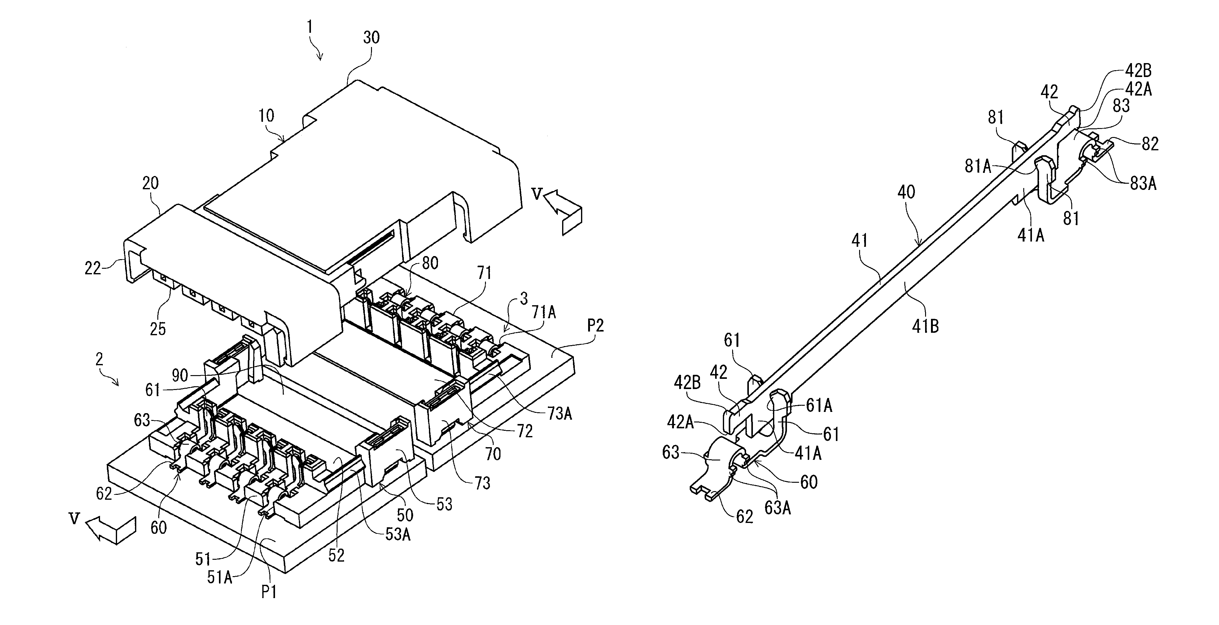
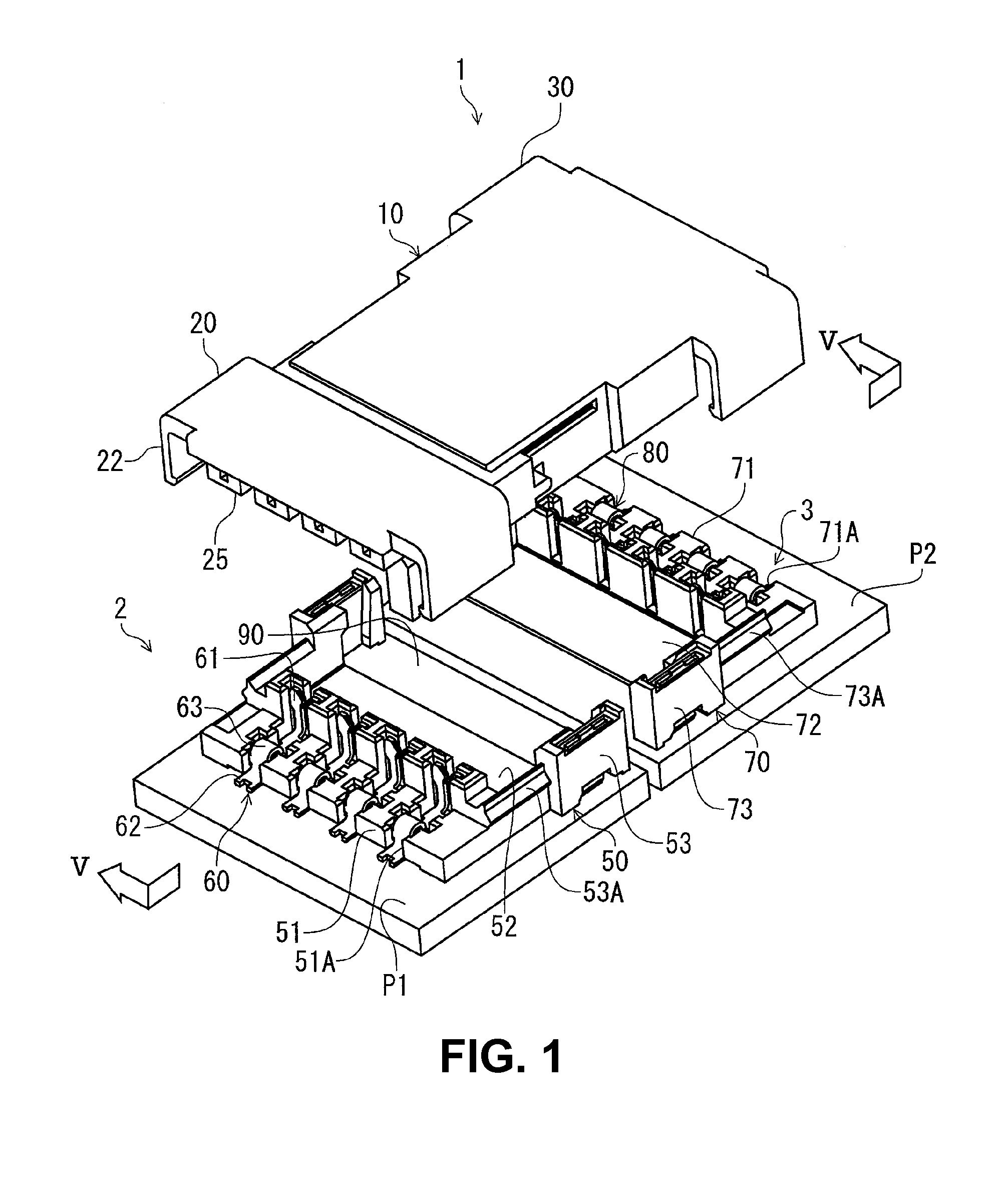
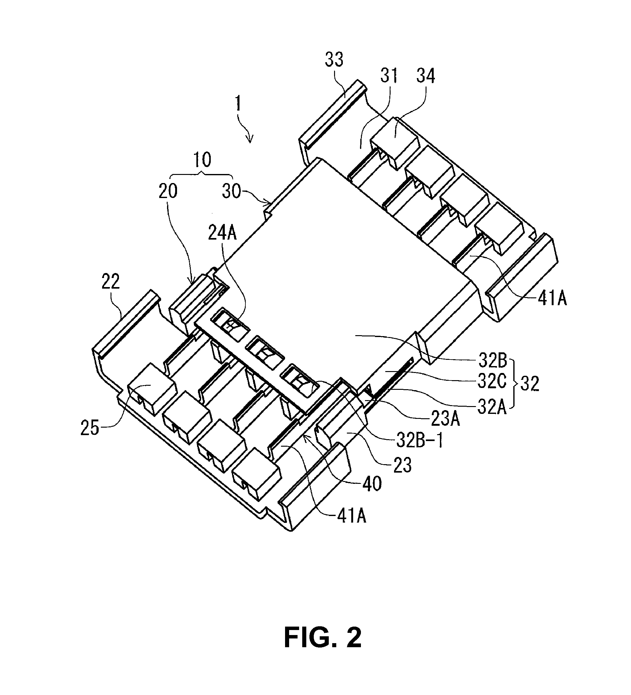
[0035]FIG. 1 is a perspective view of a joining electrical connector and board electrical connectors in the embodiment, and shows a state that is viewed from thereabove when the connectors are separated from each other. In addition, FIG. 2 is a perspective view of the joining electrical connector of FIG. 1, which is viewed from therebelow. A joining electrical connector 1 of the embodiment (hereinafter simply referred to as a joining connector 1) is fitted from thereabove to connect to the mating connectors, i.e. board electrical connectors 2 and 3 (hereinafter referred to as a board connector 2 and a board connector 3, respectively), which are respectively mounted on circuit boards P1 and P2 provided so as to have their edges face to each other on the same surface, and thereby connect the board connectors 2 and 3.

[0036]The joining connector 1 has a housing 10 that has a shape of a generally rectangular prism and is made of synthetic resin; and a plurality of joining terminals 40 (s...

second embodiment

[0092]FIG. 12 is a perspective view of a part of the joining terminal in the second embodiment. In the figure, parts that correspond to those in the first embodiment are indicated with reference numerals that are the numerals in the first embodiment plus “100”. The joining terminals 140 in the embodiment are different from the joining terminals 40 in the first embodiment, since there is a slit-like groove 141C formed to extend in the connector fitting direction between the contact section 141A and the joining section 141B, while there is no such groove formed and the joining section 41B is continuous to the contact section 41A over the whole range in the connector fitting direction in the first embodiment.

third embodiment

[0093]FIG. 13 is a perspective view of a part of the joining terminal in the third embodiment. In the figure, parts that correspond to those in the first embodiment are indicated with reference numerals that are the numerals in the first embodiment plus “200”. The joining terminals 240 in the embodiment are different from the joining terminals 40 in the first embodiment, since the extending section 242 is rolled so as to curl in the plate thickness direction, while the extending section 42 is formed to be a flat plate. In addition, the joining terminals 240 are different from the joining terminals 40 in the first embodiment since the lower end surface of each extending section 242 is flat, while there is the protrusion to be supported 42A formed to protrude from a lower end of each extending section 42.

[0094]The joining terminal 240 is supported by a support section (not illustrated) of the housing at a flat lower end surface of the extending section 242.


PUM


Abstract

A joining electrical connector connects board electrical connectors in a connector fitting direction. The joining electrical connector has a housing and a plurality of terminals arranged in the housing in a terminal arrangement direction. Each joining terminal has a main body section with contact sections to connect to each terminal of the board electrical connectors and a supported section supported by the housing in the connector fitting direction. The main body section and the supported section can move in the terminal arrangement direction responding to displacement when the relative positions of the two board electrical connectors are displaced from the regular positions. The supported section is provided so as to have at least a part thereof in the connector fitting direction overlapped with the range of the main body section in the direction.

Description

BACKGROUND OF THE INVENTION AND RELATED ART STATEMENT[0001]The present invention relates to a joining electrical connector for joining board electrical connectors, which are respectively disposed on electrical boards, with a connector fitting direction being perpendicular to board surfaces.[0002]A conventional joining electrical connector is disclosed in, for example, Patent Reference. The conventional joining electrical connector disclosed in Patent Reference includes a housing having a first support member and a second support member; and a plurality of joining terminals that are arranged in and supported by the housing and connect the first support member and the second support member.[0003]Patent Reference: Japanese Patent Application Publication No. 2010-033953[0004]In the conventional joining electrical connector disclosed in Patent Reference, each joining terminal extends in a connector fitting direction (an up-and-down direction) and has two legs to connect with the respecti...

Claims


Application Information

Patent Timeline
Patent Type & Authority Patents(United States)
IPC IPC(8): H01R12/00
CPCH01R12/732H01R31/06H01R13/112
Inventor UMEHARA, HIROKAZU
Owner HIROSE ELECTRIC GROUP
Why Eureka
Try Eureka