Wiper Control Method and Wiper Control Device

a control method and wiper technology, applied in the direction of vehicle cleaning, dynamo-electric converter control, instruments, etc., can solve the problem of limited adhesion probability on the detection surface, and achieve the effect of smooth response to chang

Inactive Publication Date: 2008-09-04
NILES PARTS CO LTD
View PDF3 Cites 1 Cited by
  • Summary
  • Abstract
  • Description
  • Claims
  • Application Information

AI Technical Summary

Benefits of technology

[0009]The present invention provides a wiper control method and a wiper control device which can smoothly respond to change of a rainfall situation by stabilizing wiping rhythm of a wiper (particularly, wiping waiting time) while ensuring required wiping.
[0021]While the adhesion cycle of the current zone is detected, the present zone is maintained. Also, when the adhesion cycle shorter than the adhesion cycle of the current zone is detected, the present zone is maintained till the upward transition condition is satisfied. By providing these transition conditions, the current zone can be maintained till the change of the rainfall situation itself is surely guaranteed, and hunting can be prevented. Also, by restricting influence by variation of the adhesion cycle, a constant adhesion cycle can be established.
[0022]The above-mentioned basic zone control method determines the intermittence time to be the basis according to the intermittence time of the current zone and performs wiping by the wiper according to this base intermittence time. Such wiping performed according to the base intermittence time is referred to as base wiping. By providing a predetermined condition for transition of the current zone, the zone transition is stabilized, the wiping waiting time by the wiper according to the zone is also stabilized, and hunting is prevented. However, according to this control method, responsiveness to temporary deterioration of visibility might be worsened.
[0025]By performing wiping based on the edge generation in this way, temporary deterioration of the visibility can be quickly responded while preventing hunting.

Problems solved by technology

As mentioned above, raindrop density is not even in the rainfall in the nature and the adhesion probability on the detection surface is limited to some extent.

Method used


Image

  • Wiper Control Method and Wiper Control Device
  • Wiper Control Method and Wiper Control Device
  • Wiper Control Method and Wiper Control Device

Examples


first preferred embodiment

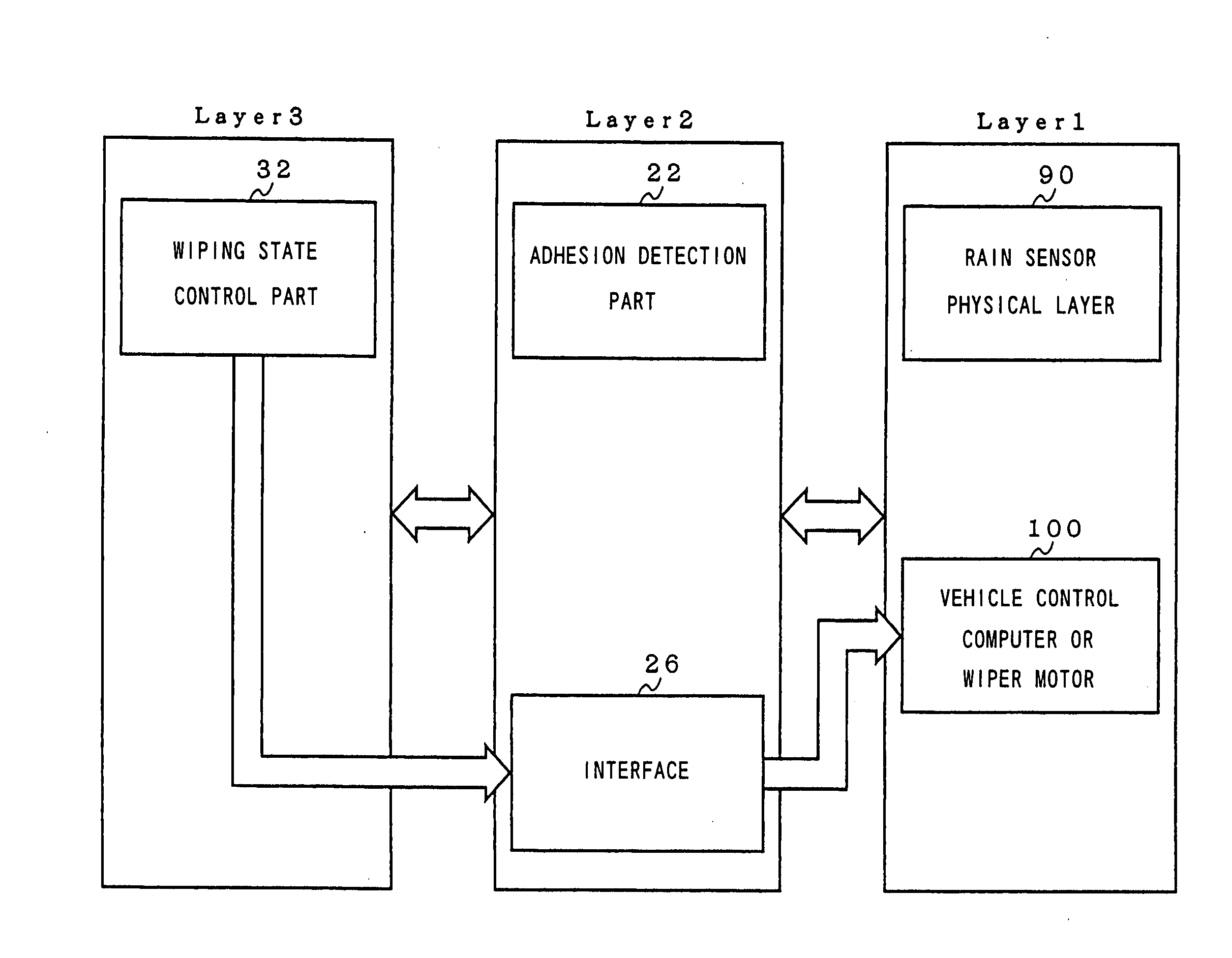
[0064]Next, the first preferred embodiment of the present invention will be described. FIG. 4 is a block diagram for explaining the construction of the wiper control device according to the first preferred embodiment of the present invention in layered structure. In FIG. 4, the wiper control device according to the first preferred embodiment of the present invention can be represented by three-layered construction, and between each of the layers, data or signals are made to communicate through a common interface such as SAP (service access point), for example. A first layer includes a rain sensor physical layer 90 and a vehicle control computer or a wiper motor 100, a second layer includes an adhesion detection part 22 and an interface 26, a third layer includes a wiping state control part 32. Each of them can be realized by software.

[0065]The rain sensor physical layer 90 is comprised by an optical mechanism and a circuit, an optical mechanism in the method that light from a light ...

second preferred embodiment

[0114]Next, a second preferred embodiment will be described. By the intermittence time control method shown in the first preferred embodiment, temporary deterioration of visibility can be responded while preventing hunting. In the meantime, the rainfall situation can rapidly change in the nature. Particularly, in the case of rapid heavy rain, immediate responsiveness is demanded for the wiper operation in order to secure visibility quickly. On the other hand, in the case of rapid drizzling rain, immediateness is not so much required. Also, in the case of the heavy rain, not the intermittence wiping but so-called continuous wiping is required. The difference between the intermittence wiping and the continuous wiping is that the continuous wiping does not have wiper waiting time.

[0115]The second preferred embodiment of the present invention is to realize continuous wiping quickly when the rainfall situation is rapidly changed to heavy rain. In concrete, this is realized by providing t...

third preferred embodiment

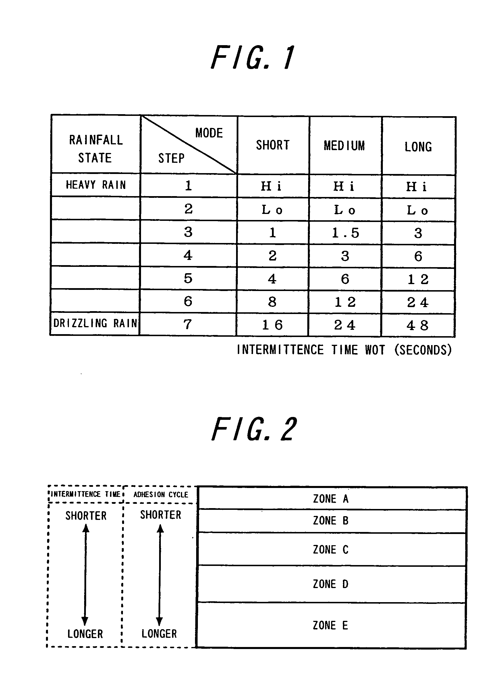
[0171]Next, the third preferred embodiment of the present invention will be described. In the above preferred embodiments, description was made supposing that the intermittence time allocated to each of the zones is 1 for convenience. If the diameters of all the raindrops are the same, it is only necessary to determine the intermittence time based only on the adhesion cycle. However, based on the consideration by the inventors, it was confirmed that the diameters of raindrops in the nature are varied, and the larger the diameter becomes, the more easily the visibility is interfered in a short time. Therefore, even with the same adhesion cycle, it is preferable that wiping is performed in a shorter time if the diameter of the raindrops is large. The third preferred embodiment of the present invention satisfies such a necessity.

[0172]In the third preferred embodiment of the present invention, a plurality of intermittence times are allocated to each zone and an appropriate intermittenc...


PUM

PropertyMeasurementUnit
adhesionaaaaaaaaaa
timeaaaaaaaaaa
intermittence timeaaaaaaaaaa

Abstract

A wiper control method and a wiper control device which can stabilize wiping rhythm of a wiper while ensuring required wiping and smoothly respond to change of a rainfall situation are provided. An adhesion cycle of a raindrop adhering on a detection surface is detected, a current adhesion cycle to be the basis when determining an intermittence time of a wiper is determined based on the detected raindrop adhesion cycle, the wiper intermittence time is determined based on the current adhesion cycle, a raindrop adhesion cycle shorter than the current adhesion cycle is detected, and when the raindrop adhesion cycle shorter than the current adhesion cycle is detected a predetermined number of times, the current adhesion cycle is changed to a shorter adhesion cycle and the wiper intermittence time is determined based on the changed current adhesion cycle.

Description

FIELD OF THE INVENTION[0001]The present invention relates to a wiper control method and a wiper control device which can stabilize wiping rhythm of a wiper while ensuring required wiping and smoothly respond to change of a rainfall situation.BACKGROUND ART[0002]A conventional wiper control device is known which injects LED light or the like to a detection surface provided on a windshield, receives its reflected light by a light receiving element and controls a wiper based on an output signal of the light receiving element. In this device, the rainfall state is estimated based on the output signal of the light receiving element, and the wiping state (continuous wiping, intermittent wiping, etc.) of the wiper is determined. For example, in JP-A-4-349053, the rainfall state is divided into 7 steps, and an intermittence time is set to each of the steps (FIG. 1).[0003]Also, as another prior art, a method for detecting dynamic adhesion of raindrops (JP-A-2001-180447) and a method for eval...

Claims


Application Information

Patent Timeline
Patent Type & Authority Applications(United States)
IPC IPC(8): G08B21/20B60S1/08G01N21/17G01N21/15
CPCG01N2021/157B60S1/0818B60S1/08G01N21/17G01W1/14
Inventor KOKURYO, KAZUTOMAKINO, YOSHITERUFURUSAWA, SATOSHI
Owner NILES PARTS CO LTD
Why Eureka
Try Eureka