Apparatus and method for measuring precipitation

a precipitation apparatus and precipitation technology, applied in the field of apparatus and precipitation measurement methods, can solve the problems of inability to measure precipitation in depth, inability to provide the depth of snowfall measurement, and difficulty in measuring precipitation by electronic instruments, etc., to achieve convenient and efficient means.

Inactive Publication Date: 2007-06-14
NOONAN TECH
View PDF19 Cites 59 Cited by
  • Summary
  • Abstract
  • Description
  • Claims
  • Application Information

AI Technical Summary

Benefits of technology

[0025] By providing a convenient and efficient means of determining the density of frozen precipitation, particularly snowfall, users of snow blowing equipment may be aided in operating snow blow

Problems solved by technology

Although precipitation may be measured by manual or electronic means, electronic instruments that measure rainfall typically do not measure snowfall and vice versa.
In fact, frozen precipitation is difficult to measure by electronic instrument.
While snowfall may be measured manually by a simple gauge comprising a cylinder having a measurement scale affixed to it, snowfall is difficult to measure by electronic instrument.
These snow gauges do not provide the amount of snow fall in depth nor do they measure the “wetness” or density of the snow which would be useful in areas where snow blowing equipment is used.
This device only detects moisture or precipitation but does not measure the amount or rate of precipitation.
Thus, while the '040 patent discloses an apparatus and method for detecting the presence of precipitation and differentiating between rain and snow, the patent does not disclose a method or apparatus for measuring the amount of frozen precipitation that has fallen or t

Method used


Image

  • Apparatus and method for measuring precipitation
  • Apparatus and method for measuring precipitation
  • Apparatus and method for measuring precipitation

Examples


Embodiment Construction

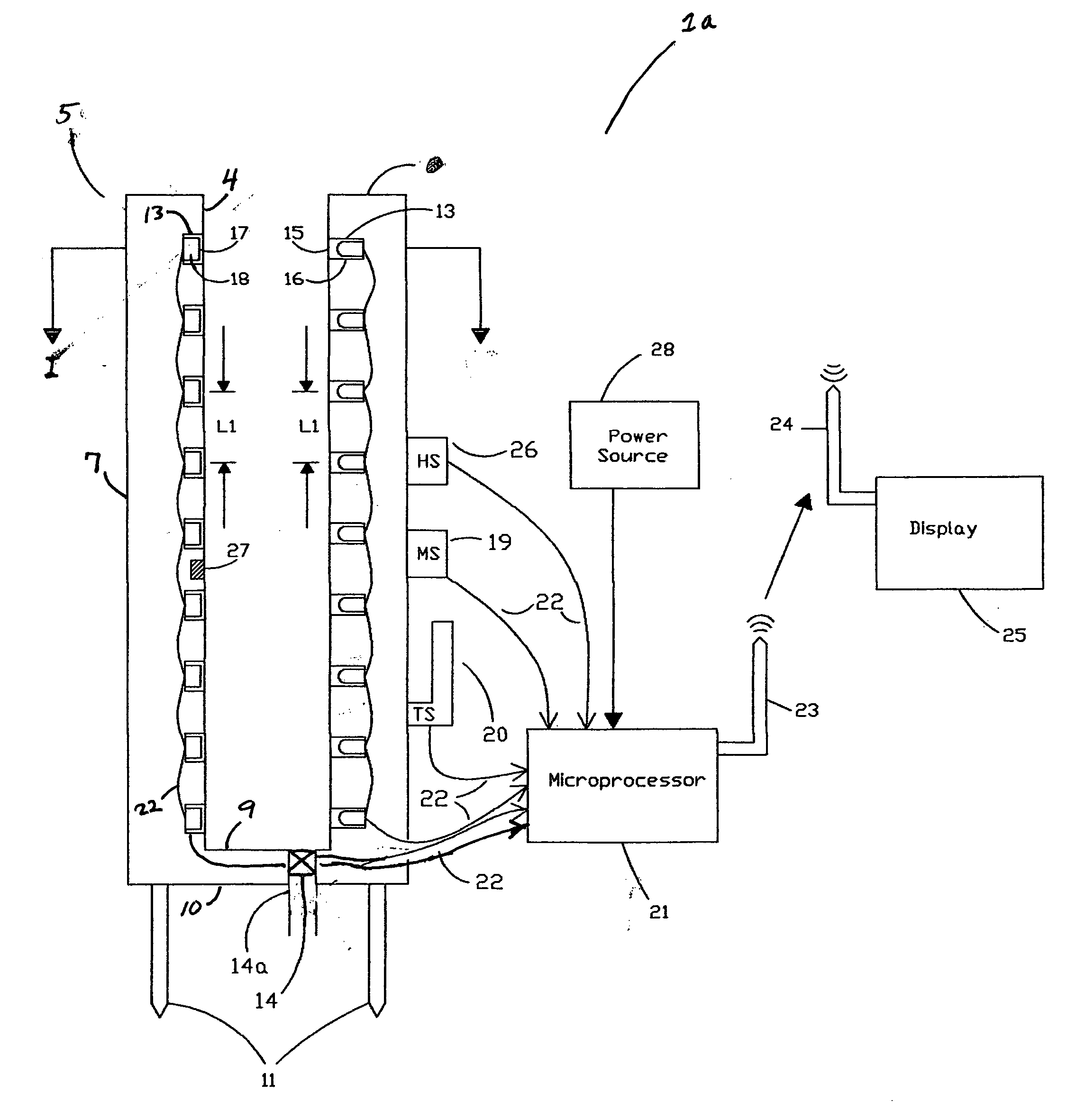
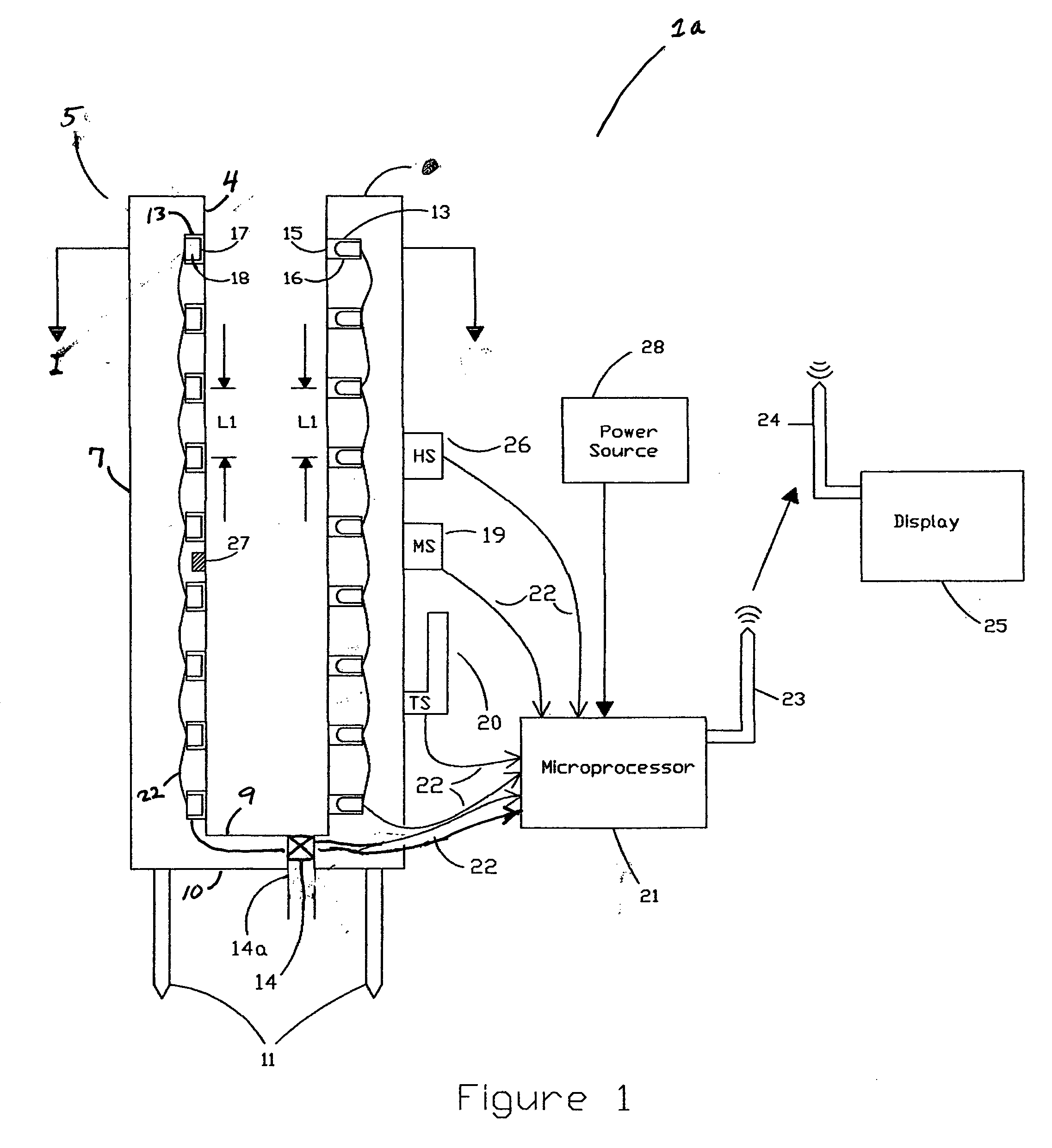
[0041] One embodiment of the present invention is shown in FIG. 1. The precipitation gauge 1a includes a support structure 5, constructed out of metal, plastic or other suitable material, on which a plurality of light sources 16 and corresponding light sensors 18 are mounted in a vertical arrangement. Each of the light sources 16 are spaced a predetermined distance “L1” from each adjacent light source 16. Each light sensor 18 is also spaced a predetermined distance “L1” from each adjacent light sensor 18. The lowest light sensor 18 and the lowest light source 16 are placed a predetermined distance, preferably “L1”, above the inner bottom wall of the support structure 5. The distance between each light sensor 18 is preferably the same distance as is between each light source 16 but the two distances may be unequal. The support structure 5 may include projections or spikes 11 on the outer bottom wall 3 of the support structure 5 so that the apparatus may be secured to the ground. Alte...


PUM


Abstract

A precipitation gauge for measuring liquid and frozen precipitation is provided according to the present invention that includes a support structure having at least one light sensor, or pair of electrodes, and at least one light source disposed thereon so that the light sensor may receive light that is emitted from the light source. The light sensor or light sensors and the light source or light sources generally extend a substantial height of the support structure. The light sensor or light sensors generate an output signal in response to the amount of light received from the light source. A microprocessor receives the output signal or output signals from the light sensor or light sensors and determines whether precipitation is present between the light sensor or light sensors and the light source or light sources. Based on the output signal or output signals, the microprocessor determines and displays the level of precipitation. The microprocessor may also determine the density of frozen precipitation.

Description

CROSS REFERENCE TO RELATED APPLICATIONS [0001] This application claims the benefit of U.S. Provisional Application Ser. No. 60 / 738,086 filed Nov. 19, 2005.BACKGROUND OF THE INVENTION [0002] Although precipitation may be measured by manual or electronic means, electronic instruments that measure rainfall typically do not measure snowfall and vice versa. In fact, frozen precipitation is difficult to measure by electronic instrument. While snowfall may be measured manually by a simple gauge comprising a cylinder having a measurement scale affixed to it, snowfall is difficult to measure by electronic instrument. [0003] Snowfall may be measured electronically by a gauge that melts the snow to water and converts the amount of snow fall to a liquid equivalent. U.S. Pat. No. 6,044,699 discloses such a gauge. The gauge comprises a support structure or an open cylinder, a reservoir for collecting precipitation, means for weighing the reservoir and electronic means for converting the weight me...

Claims


Application Information

Patent Timeline
IPC IPC(8): G01W1/00
CPCG01W1/14
Inventor DUFAUX, DOUGLAS PAULHIGGINS, JOHN PAUL
Owner NOONAN TECH
Why Eureka
Try Eureka