Water jet mechanism for whirlpool effect in pedicures or other applications

a technology of water jet and pedicure, which is applied in the field of water jet mechanism and method of use in pedicure, can solve the problems of water leakage around the shaft, requiring maintenance, and difficult cleaning and sterilization, and achieves the effect of rapid and easy cleaning and sterilization

Active Publication Date: 2007-06-21
LEXOR MFG LLC
View PDF5 Cites 31 Cited by
  • Summary
  • Abstract
  • Description
  • Claims
  • Application Information

AI Technical Summary

Benefits of technology

[0009]It is an object of the invention to provide a system for circulating water in a bath used in a

Problems solved by technology

There is frequently water leakage around the shaft requiring maintenance.
Also, the pipe system is subject to accumulation of dirt, mold and bacteria

Method used


Image

  • Water jet mechanism for whirlpool effect in pedicures or other applications
  • Water jet mechanism for whirlpool effect in pedicures or other applications
  • Water jet mechanism for whirlpool effect in pedicures or other applications

Examples


Embodiment Construction

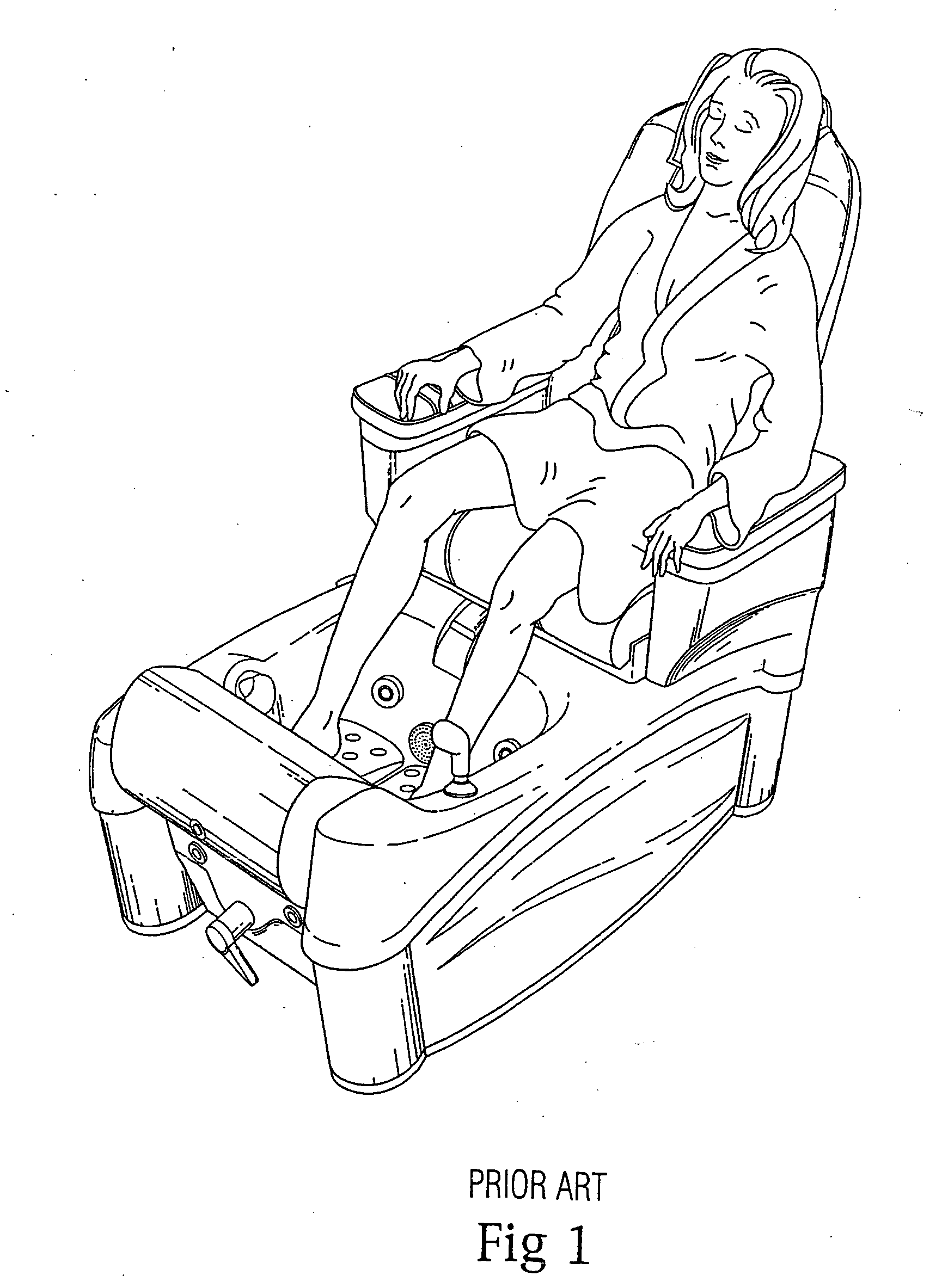
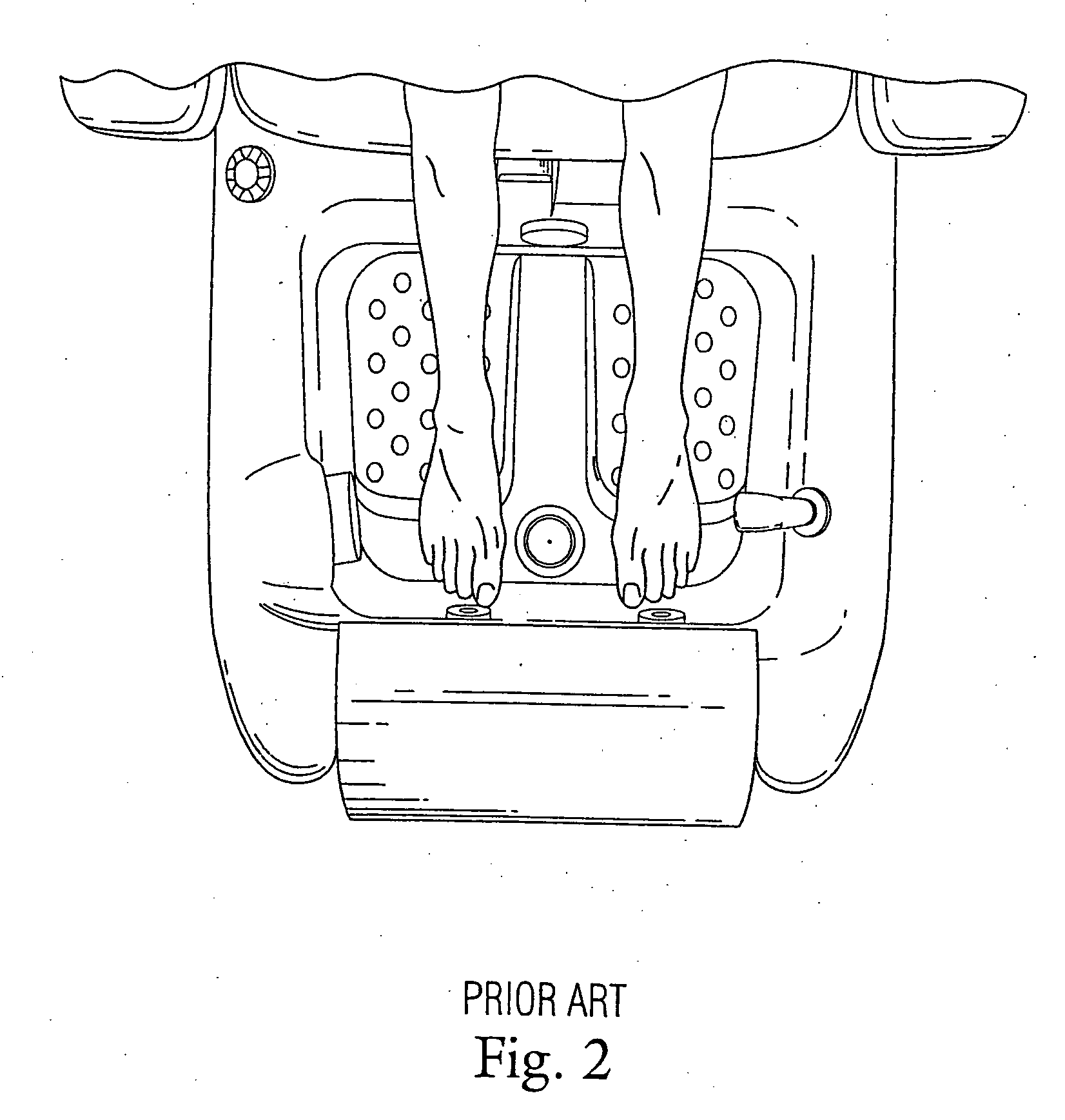
[0041]As shown in FIGS. 1 and 2, persons receiving a pedicure are usually seated in a pedicure chair 10 which has a basin 12 in which the person's feet are placed. Water is circulated in the basin 12 and is directed at the person's feet.

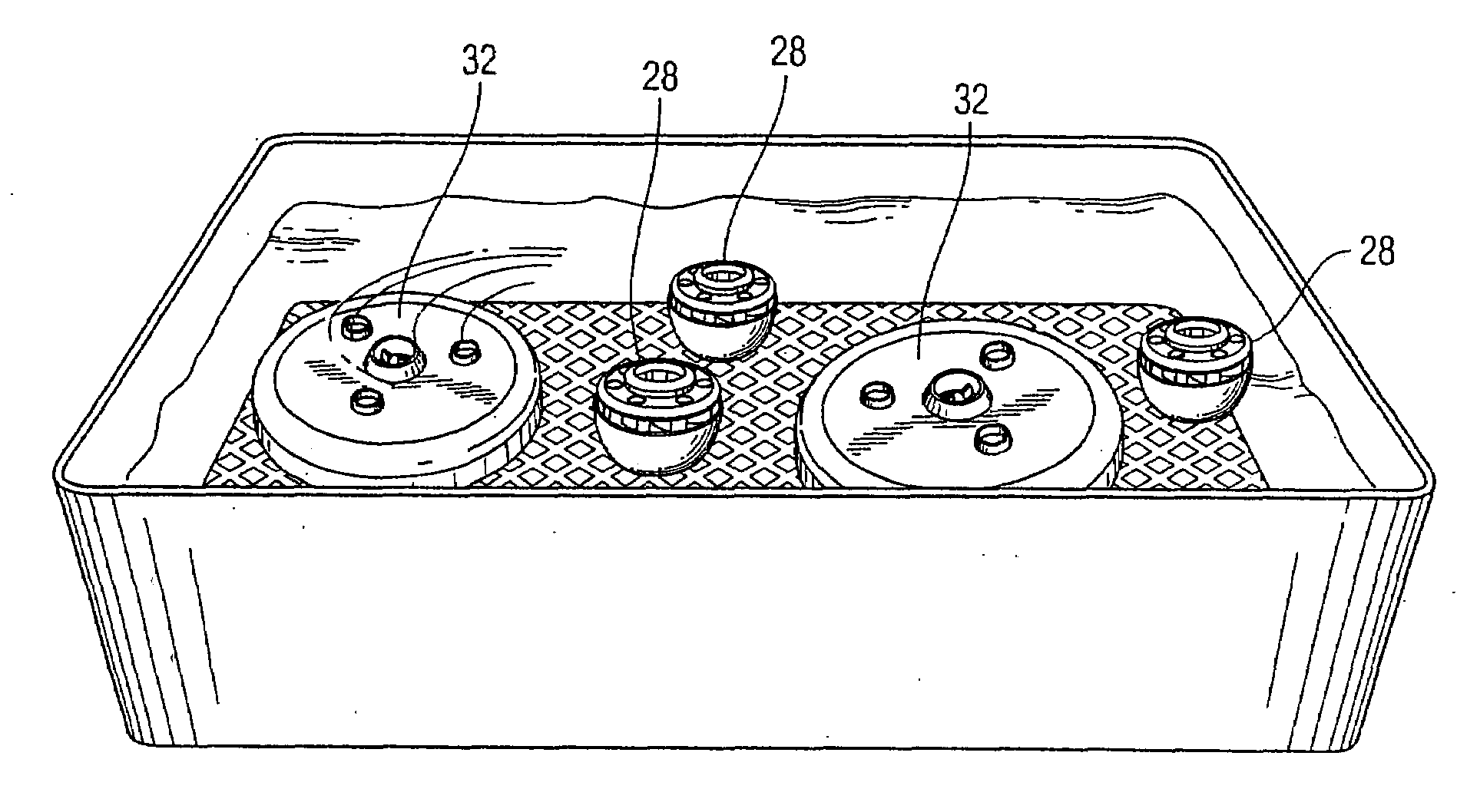
[0042]The jet pump of the present invention is shown in FIG. 3. As shown in FIGS. 4-5, a housing 14 has external threads 16 formed thereon. The first end of the housing has an enlarged shoulder 18 formed thereon. A cooperating threaded screw ring 20 is mounted on the threaded housing 14. A first seal ring 22 is disposed adjacent to the enlarged shoulder 18 on the housing and a second seal ring 24 is disposed adjacent to the screw ring 20. The basin 12 has an opening formed in the sidewall or bottom of the basin and the housing 14 is received in the opening with the seal rings 22, 24 on either side of the opening in the sidewall of the basin. Tightening of the screw ring 20 against the basin forms a watertight seal with the respective first seal ring ...


PUM


Abstract

A whirlpool foot bath for a pedicure chair having a housing with a removable cap and a rotor and stator magnetic motor within the housing. Water in the bath is circulated through an inlet in the cap and out through at least one outlet in the cap. A method of use is described.

Description

CROSS REFERENCE TO RELATED APPLICATIONS[0001]This application is a continuation-in-part of application Ser. No. 11 / 312,907 filed Dec. 20, 2005. The contents and disclosure of which are hereby incorporated by reference herein in their entirety.BACKGROUND OF THE INVENTION[0002]1. Field of the Invention[0003]The present invention relates to a water jet mechanism and method of use in a pedicure and more particularly, to a motor in a housing having a cap.[0004]2. Description of Related Art[0005]It is known to have a pedicure chair with a basin for bathing the feet of a person (U.S. Patent D454,705 to Long). These types of pedicure chairs have a pipe system to introduce water into, and remove water from, the basin. The water is circulated by a conventional motor-driven, shaft mounted, fan. There is frequently water leakage around the shaft requiring maintenance. Also, the pipe system is subject to accumulation of dirt, mold and bacteria and is very difficult to clean and sterilize after u...

Claims


Application Information

Patent Timeline
IPC IPC(8): A47K3/022
CPCA61H35/006A61H2203/0431
Inventor LONG, CHRISTOPHER L.
Owner LEXOR MFG LLC
Why Eureka
Try Eureka