Curved Liquid-Crystal Display Device and Backlight Used for Curved Liquid-Crystal Display Device

a liquid crystal display device and backlight technology, which is applied in the direction of optical elements, lighting and heating apparatus, instruments, etc., can solve the problems of uniformity of light emitted from the light source inside the backlight, the difference in viewing angle, and the loss of uniform light in the peripheral edges of the concavely curved liquid crystal panel. , to achieve the effect of uniform brightness within the display area

Inactive Publication Date: 2007-06-28
INFOVISION OPTOELECTRONICS HLDG LTD
View PDF8 Cites 89 Cited by
  • Summary
  • Abstract
  • Description
  • Claims
  • Application Information

AI Technical Summary

Benefits of technology

[0013]Accordingly, it is an object of the present invention to provide a backlight with which the uniformity of brightness within a display area of a concavely curved liquid crystal display device is improved while fulfilling the demand for slimmer display devices, as well as a curved liquid-crystal display device including such a backlight.

Problems solved by technology

But a problem with increasingly larger television LCD screens is that the viewing angle difference between the viewing angle when the viewer views the center portion of the screen and the viewing angle when the viewer views the left and right edges of the screen increases (throughout this specification, the technical term “viewing angle” is defined as the angle between the line of sight of the viewer viewing the screen and the tangent to the intersection between the line of sight and the observed screen surface, and the difference between the center and left / right edge viewing angles is defined as and used to mean the “viewing angle difference”).
Furthermore, another problem with large-scale television LCD screens is that glare off the screens also increases.
However, even when the viewing angle difference is improved by a liquid-crystal panel with a concavely curved screen (referred to as “concavely curved liquid-crystal panel” below), when using a backlight with the same structure as that of a conventional flat liquid-crystal panel for such a concavely curved liquid-crystal panel, there is the problem that the uniformity of light that is emitted from the light source inside the backlight is lost in particular at the peripheral edges of the concavely curved liquid-crystal panel.
As a result, the image quality of the concavely curved liquid-crystal panel becomes lower than that of the screen of a conventional flat liquid-crystal display device.

Method used


Image

  • Curved Liquid-Crystal Display Device and Backlight Used for Curved Liquid-Crystal Display Device
  • Curved Liquid-Crystal Display Device and Backlight Used for Curved Liquid-Crystal Display Device
  • Curved Liquid-Crystal Display Device and Backlight Used for Curved Liquid-Crystal Display Device

Examples


embodiment 1

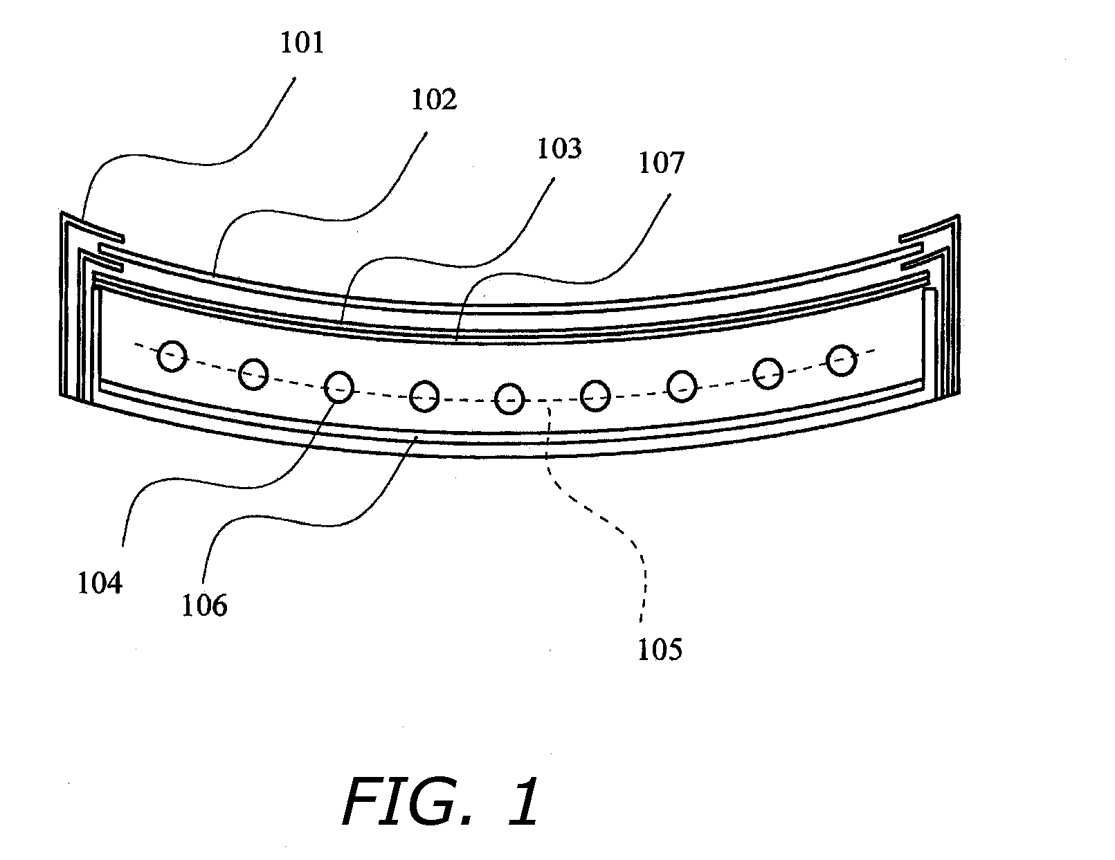
[0065]FIG. 1 is a diagrammatic sectional view illustrating the structure of a direct backlight for a liquid-crystal display device having a concavely curved panel according to Embodiment 1.

[0066]In FIG. 1, numeral 101 denotes a bezel, numeral 102 denotes a liquid-crystal panel, numeral 103 denotes an optical sheet, numeral 104 denotes cold cathode luminescent lamps, numeral 107 denotes a scattering plate, numeral 106 denotes a reflective sheet and numeral 105 denotes a surface including the tube center axes of the cold cathode luminescent lamps. It should be noted that the cold cathode luminescent lamps 104 have a straight tubular shape in the present embodiment. The arrangement of the liquid-crystal panel 102, the optical sheet 103, the scattering plate 107 and the cold cathode luminescent lamps 104 is explained using an exploded view.

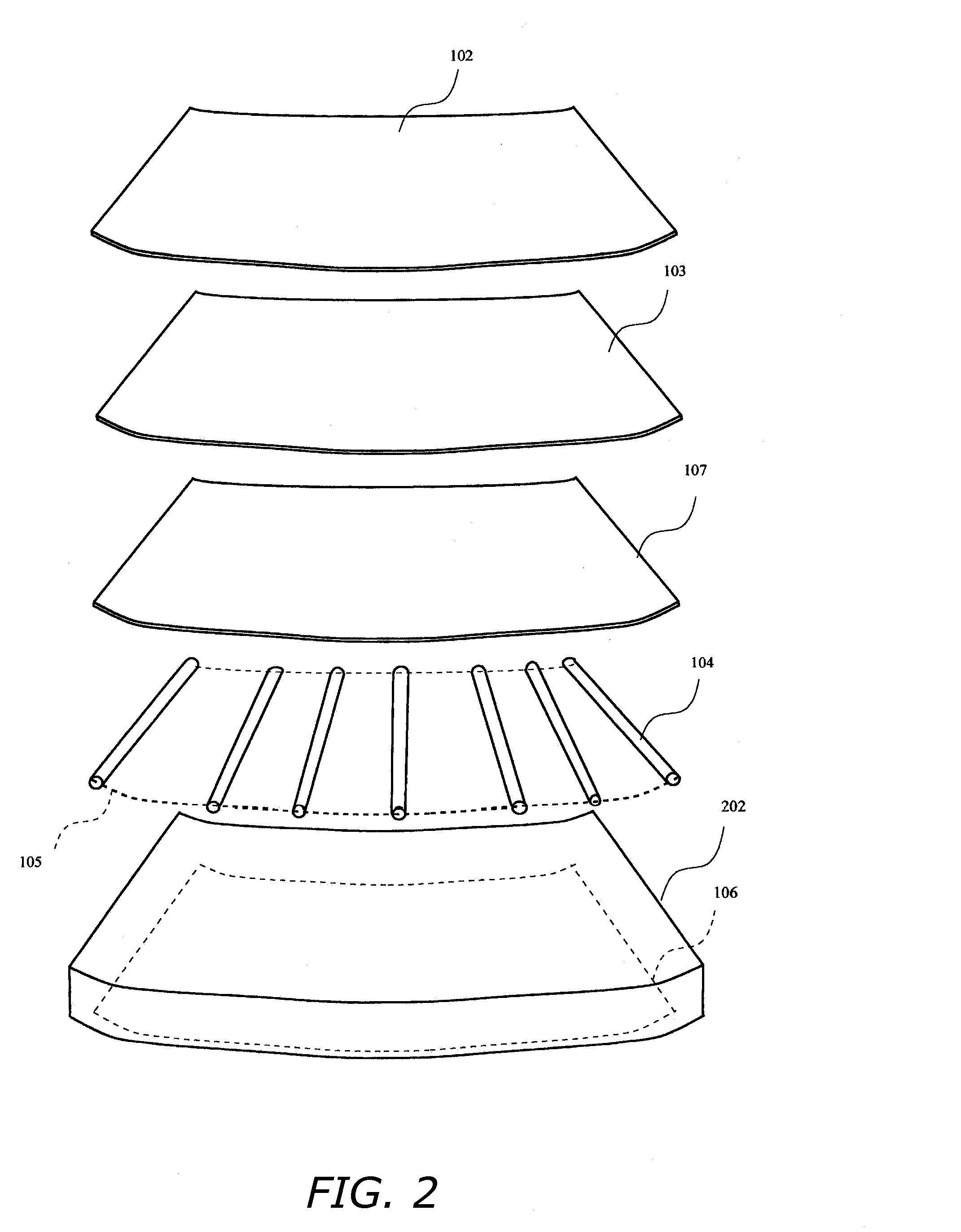
[0067]FIG. 2 illustrates a backlight for a liquid-crystal display device having a concavely curved liquid-crystal panel according to Embodiment 1 and...

embodiment 2

[0070]FIG. 3 is a diagrammatic sectional view illustrating the structure of a direct backlight for a liquid-crystal display device having a concavely curved panel according to Embodiment 2.

[0071]In FIG. 3, numeral 104 denotes cold cathode luminescent lamps. Furthermore, numeral 105 denotes a surface including the tube center axes of the cold cathode luminescent lamps 104.

[0072]FIG. 4 illustrates the structure of a backlight for a liquid-crystal display device having a concavely curved liquid-crystal panel according to Embodiment 2 and is a diagrammatic exploded view of the liquid-crystal panel 102, the optical sheet 103, the scattering plate 107, the cold cathode luminescent lamps 104 and the backlight unit's frame 202, which are its principal components.

[0073]The cold cathode luminescent lamps 104 have the same concavely curved shape as the curved liquid-crystal panel 102. Furthermore, as shown in FIG. 4, a plurality of the cold cathode luminescent lamps 104 are arranged next to ea...

embodiment 3

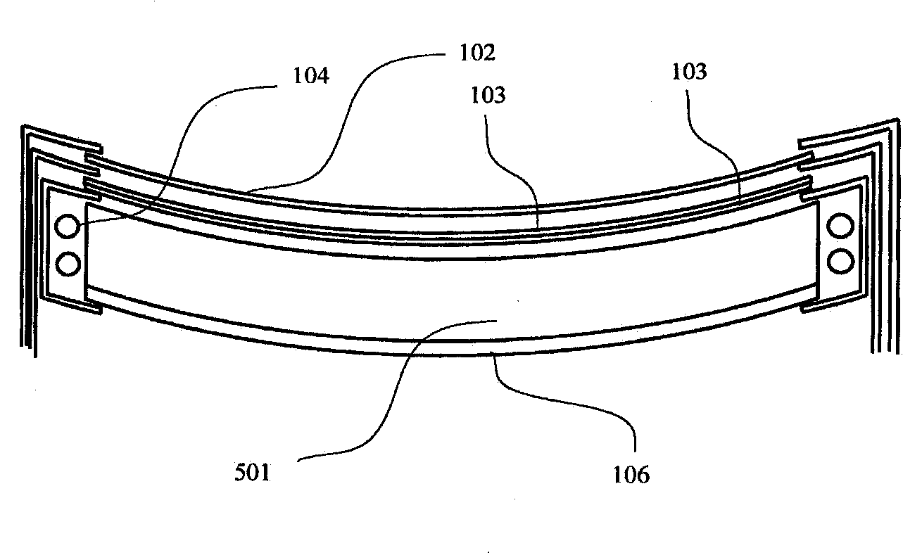
[0075]FIG. 5 is a diagrammatic sectional view illustrating the structure of a side backlight for a liquid-crystal display device having a concavely curved liquid-crystal panel according to Embodiment 3.

[0076]In FIG. 5, numeral 104 denotes cold cathode luminescent lamps and numeral 501 denotes a light-conductive plate.

[0077]FIG. 11 illustrates a backlight used for the liquid-crystal display device having a concavely curved liquid-crystal panel according to Embodiment 3 and is a diagrammatic exploded view of the liquid-crystal panel 102, the optical sheets 103, the light-conductive plate 501, the cold cathode luminescent lamps 104 and the backlight unit's frame 202, which are its principal components. It should be noted that in this Embodiment 3, two optical sheets 103 are used, but also in the other embodiments, there is no particular limitation to the number of optical sheets, and the number of optical sheets can be chosen as appropriate.

[0078]In the backlight used for the liquid-cr...


PUM

PropertyMeasurementUnit
shapeaaaaaaaaaa
light-conductiveaaaaaaaaaa
viewing angleaaaaaaaaaa

Abstract

Backlight with which the uniformity of brightness within a display area of a concavely curved liquid crystal display device is improved while fulfilling the demand for slimmer liquid-crystal display devices, as well as curved liquid-crystal display device including such a backlight. The shape of a frame, an optical sheet, and a scattering plate constituting the backlight unit is the same concavely curved shape as that of the concavely curved panel; and the liquid-crystal panel, the optical sheet, and cold-cathode luminescent lamps are arranged such that the concavely curved panel, the surface of a frame constituting the backlight unit that faces the concavely curved panel, an optical sheet surface, and a surface including the tube center axes of a plurality of cold-cathode luminescent lamps are parallel to each other.

Description

BACKGROUND OF THE INVENTION[0001]1. Technical Field[0002]The present invention relates to curved liquid-crystal display devices and to backlights used for curved liquid-crystal display devices.[0003]2. Description of the Related Art[0004]In recent years, as liquid crystal display devices have come to be used as display devices of television receivers, the screens of such liquid crystal display devices have become increasingly bigger. But a problem with increasingly larger television LCD screens is that the viewing angle difference between the viewing angle when the viewer views the center portion of the screen and the viewing angle when the viewer views the left and right edges of the screen increases (throughout this specification, the technical term “viewing angle” is defined as the angle between the line of sight of the viewer viewing the screen and the tangent to the intersection between the line of sight and the observed screen surface, and the difference between the center and...

Claims


Application Information

Patent Timeline
Patent Type & Authority Applications(United States)
IPC IPC(8): G02F1/1333G02F1/1335F21S2/00F21Y101/00F21Y103/00G02F1/13357
CPCG02B6/0051G02B6/0055G02B6/0068G02B6/0071G02B6/0088G02F1/133602G02F1/133611
Inventor NOUCHI, MASANORIMATSUDA, FUMITOSHIHASHIBA, HIROMITSU
Owner INFOVISION OPTOELECTRONICS HLDG LTD
Why Eureka
Try Eureka