Electrical connector with improved soldering characteristic to be mounted on a printed circuit board

a technology of printed circuit board and soldering characteristic, which is applied in the direction of coupling device connection, two-part coupling device, electrical apparatus, etc., can solve the problems of easy warpage, thin insulating housing, and inability to mount the electrical connector in the electrical devi

Inactive Publication Date: 2007-06-28
HON HAI PRECISION IND CO LTD
View PDF4 Cites 121 Cited by
  • Summary
  • Abstract
  • Description
  • Claims
  • Application Information

AI Technical Summary

Benefits of technology

[0007] In order to attain the objective above, an electrical connector mounted on a PCB comprises an insulative housing and a plurality of contacts retained in the insulative housing. The insulative housing comprises a base extending along a longitudinal direction and a mating portion protruding forwardly from a front surface of the base. The mating portion defines a receiving hole extending into the base for receiving the plug. The base has a mounting wall facing to the PCB with a slot defined therethrough in another direction perpendicular to the longitudinal direction. The slot extends forwardly substantially along the longitudinal direction from a position of the mounting wall. The slot extends through the mating portion and in communication with the receiving hole. The contacts have a plurality of contact portions extending into the receiving hole. With this arrangement, the slot can counteract a deformation of the insulative housing to ensure the soldering tails of the contacts coplanar with one another, thereby facilitating the contacts to be mounted on the PCB.

Problems solved by technology

However, with a trend that electrical devices have lower profile, the electrical connectors mounted in the electrical devices are accordingly smaller and smaller.
Meanwhile, the insulative housing becomes so thin that it may easily be warpaged, especially the side walls.
As a result, the soldering portions of the contacts cannot be coplanar with one another anymore due to the deformation of the insulative housing and the contacts retained in the insulative housing can't be wonderfully mounted on the PCB to ensure a reliable signal transmission.

Method used


Image

  • Electrical connector with improved soldering characteristic to be mounted on a printed circuit board
  • Electrical connector with improved soldering characteristic to be mounted on a printed circuit board
  • Electrical connector with improved soldering characteristic to be mounted on a printed circuit board

Examples


Embodiment Construction

[0015] Reference will now be made in detail to the preferred embodiment of the present invention.

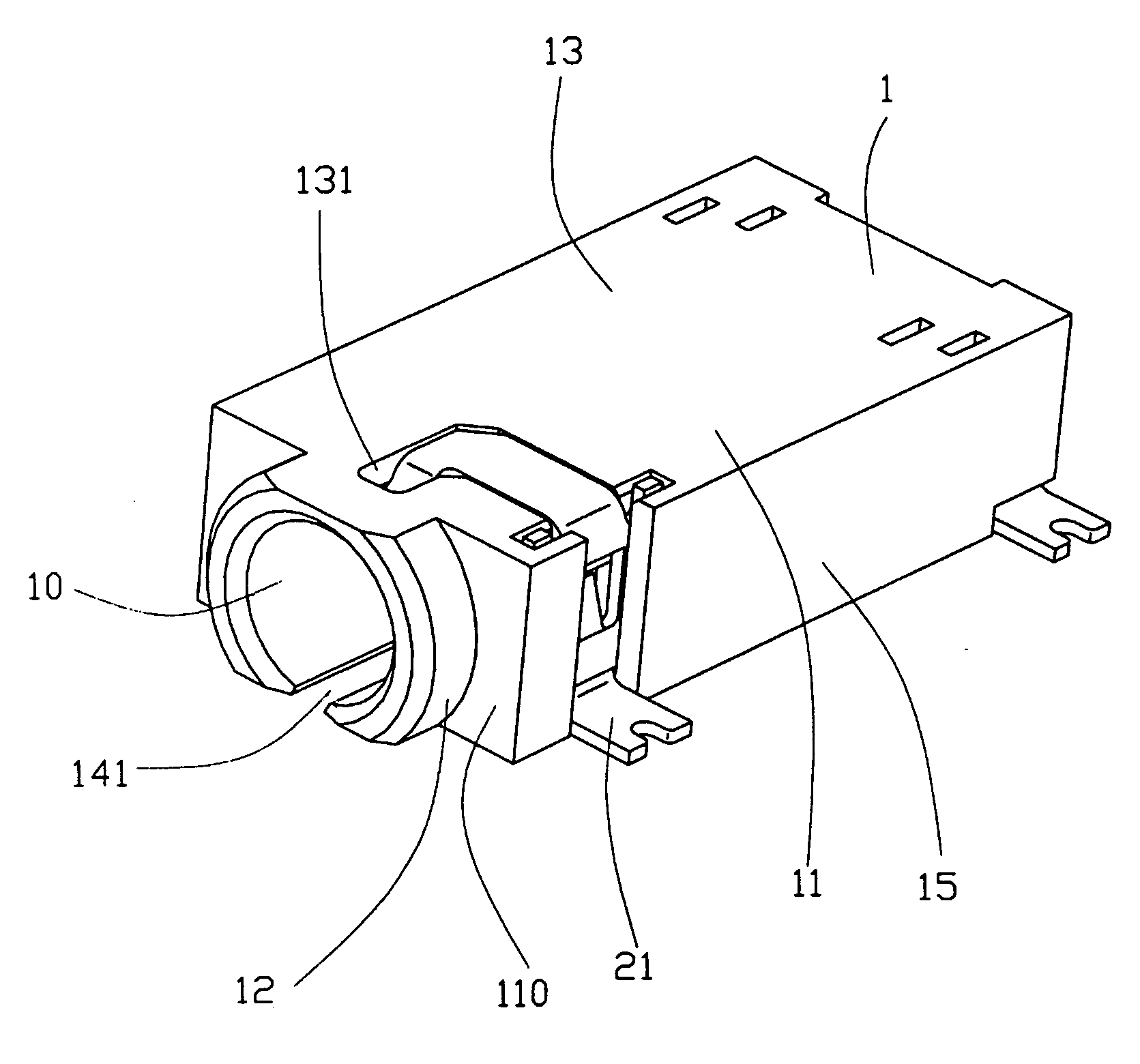
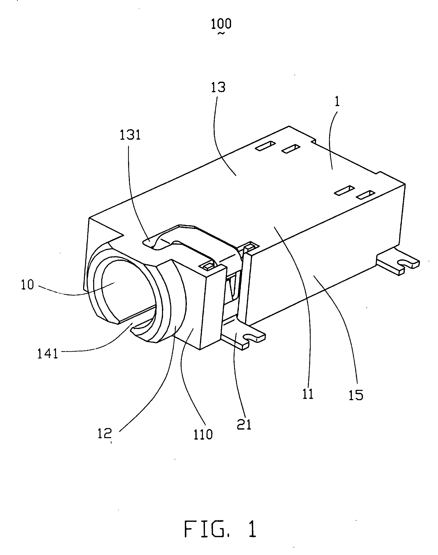
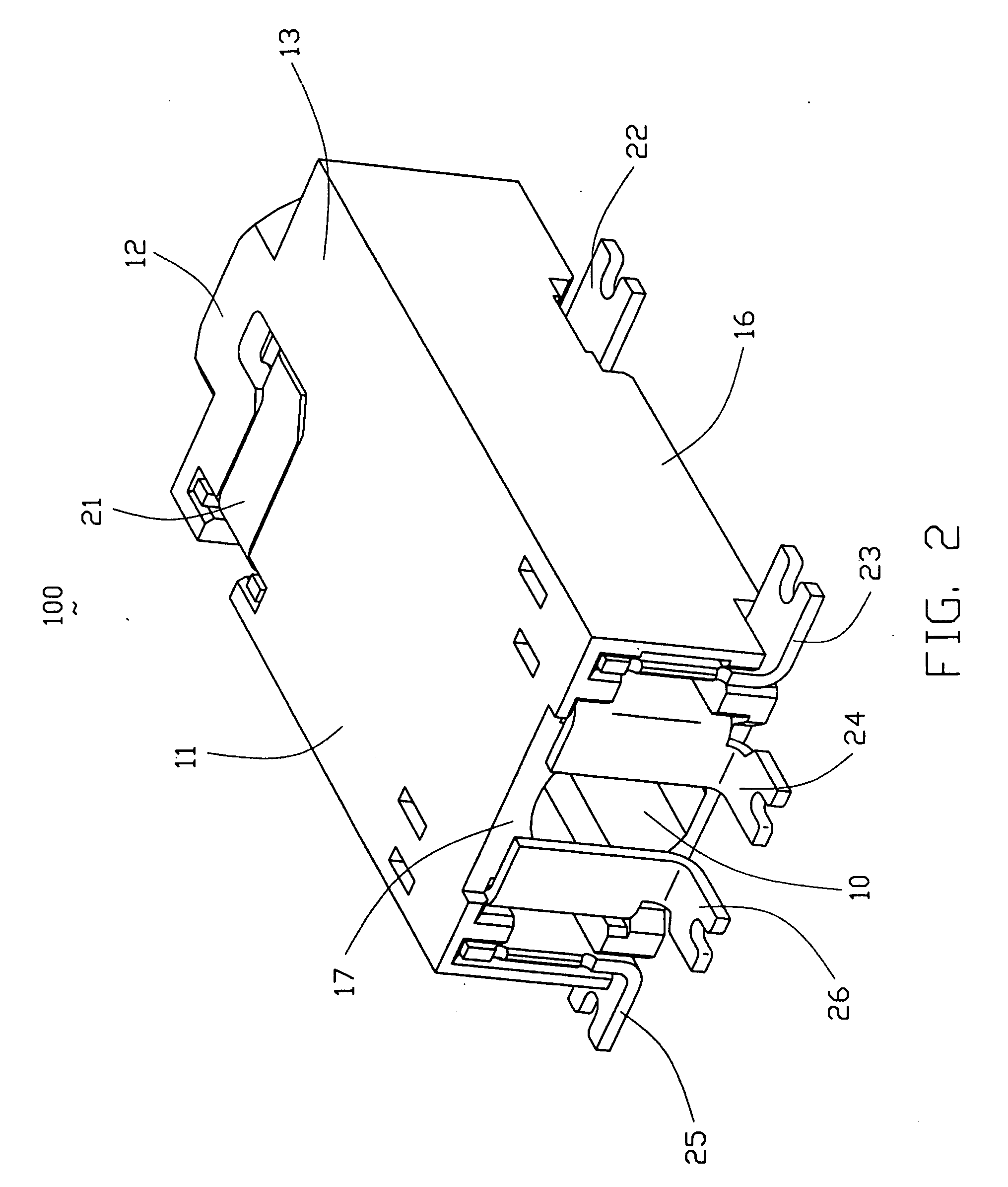
[0016] Referring to FIGS. 1 to 5, an electrical connector 100 according to the preferred embodiment is an audio jack connector mounted on a PCB 4 for mating with a corresponding plug 200 (shown in FIG. 5). The electrical connector 100 comprises an insulative housing 1 and a plurality of contacts 2 retained in the insulative housing 1. The contacts 2 include a first contact 21, a second contact 22, a first switch terminal group and a second switch terminal group.

[0017] The insulative housing 1 has a front face (not labeled) for engaging with the plug 200, a rectangular-shaped base 11 and a mating portion 12 extending forwardly from a front surface 110 of the base 11. The base 11 extends along a longitudinal direction. The mating portion 12 defines a receiving hole 10 extending inwardly through the base 11 in the longitudinal direction. The base 11 has a top wall 13, a mounting wall 14 o...


PUM


Abstract

An electrical connector (100) includes an insulative housing (1) for receiving a number of contacts (2). The insulative housing has a base (11) extending in a longitudinal direction and a mating portion (12) protruding forwardly from the base. The base (11) defines a slot (141) from an intermediate position thereof and extending forwardly through the mating portion (12). The mating portion (12) defines a receiving hole (10) extending into the base (11). The receiving hole (10) is in communication with the slot (141). The slot (141) can counteract a deformation of the insulative housing to ensure the soldering tails (213, 223, 233, 243, 253, 262) of the contacts coplanar with one another, thereby ensuring the contacts to be wonderfully surface mounted on a PCB.

Description

BACKGROUND OF THE INVENTION [0001] 1. Field of the Invention [0002] This invention generally relates to an electrical connector, and more particularly to an electrical connector with improved soldering characteristic to be mounted on a print circuit board (PCB). [0003] 2. Description of the Prior Art [0004] U.S. Pat. No. 6,690,801 B2, discloses a conventional electrical connector which includes an insulative housing and a plurality of contacts assembled to the insulative housing. The insulative housing has a top wall, a mounting wall and a pair of side walls connecting the top and mounting walls. The insulative housing further defines a longitudinal hole therethrough for receiving a mating plug. The contacts each have a soldering portion coplanar with one another to be surface mounted on a PCB. However, with a trend that electrical devices have lower profile, the electrical connectors mounted in the electrical devices are accordingly smaller and smaller. Meanwhile, the insulative ho...

Claims


Application Information

Patent Timeline
Patent Type & Authority Applications(United States)
IPC IPC(8): H01R24/04H01R24/58
CPCH01R24/58H01R2107/00H01R12/707
Inventor LONG, JI-ENKUO, WEI-NAN
Owner HON HAI PRECISION IND CO LTD
Why Eureka
Try Eureka