Method for automatic differentiation of weld signals from defect signals in long-range guided-wave inspection using phase comparison

a technology of phase comparison and weld signal, which is applied in the direction of mechanical measurement arrangement, mechanical roughness/irregularity measurement, instruments, etc., can solve the problems of specific problems, time-consuming analysis of test data, and difficulty in proper identification of geometric feature signals

Active Publication Date: 2007-06-28
SOUTHWEST RES INST
View PDF0 Cites 11 Cited by
  • Summary
  • Abstract
  • Description
  • Claims
  • Application Information

AI Technical Summary

Benefits of technology

[0017] In fulfillment of the stated objectives the present invention provides a method that takes advantage of all of the benefits associated with magnetostrictive sensor investigation of longitudinal structures and incorporates steps that allow for the automatic differentiation of the various types of reflected signals that are received in the process. The methodology is based on an ability to characterize reflected waves as having been generated (reflected) by a “step-up” or a “step-down” feature

Problems solved by technology

Such structures present specific problems for the investigation and/or monitoring of locations as much as 100 feet from the placement of an NDE type sensor system.
Anomalies in the structure that cause a wave reflection include defects (such as corrosion wall loss areas and cracks) and geometric features in the structure (such as welds, weld attachments, and clamps).
In cases where the section of the s

Method used


Image

  • Method for automatic differentiation of weld signals from defect signals in long-range guided-wave inspection using phase comparison
  • Method for automatic differentiation of weld signals from defect signals in long-range guided-wave inspection using phase comparison
  • Method for automatic differentiation of weld signals from defect signals in long-range guided-wave inspection using phase comparison

Examples


Embodiment Construction

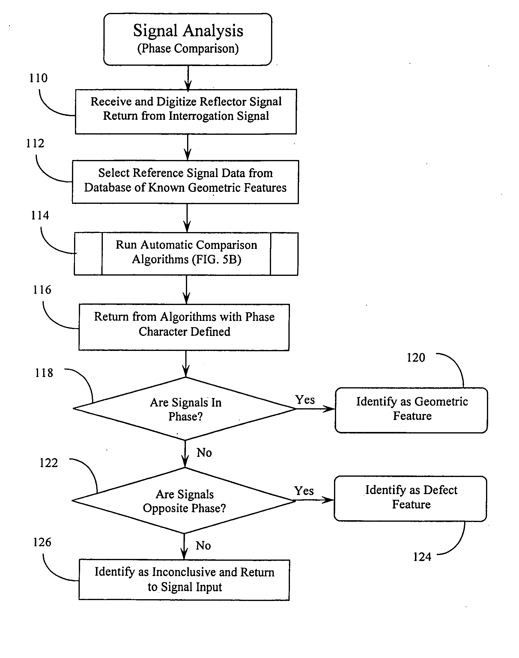
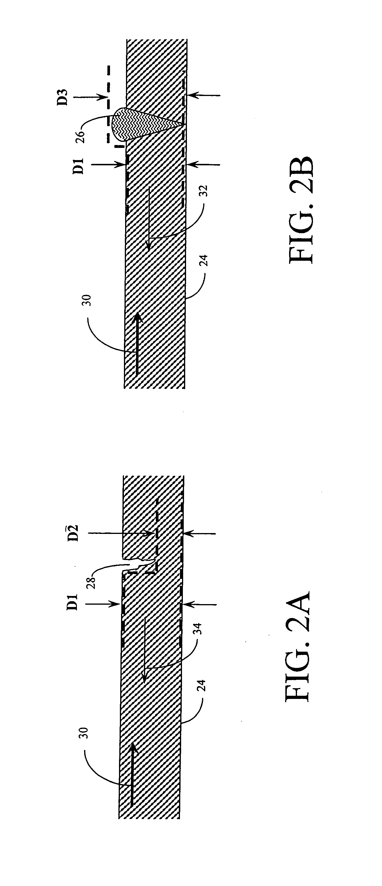
[0027] As summarized above, when an incident guided wave propagating along a structure encounters an increased cross-sectional area (for example, welds, weld attachments, and clamps), the wave reflected from that anomaly has the same phase as the incident wave. When the incident wave encounters a decreased cross-sectional area (as in defect locations), the reflected wave has an opposite phase to the incident wave. To illustrate the above, the experimentally measured incident waveform in a pipe and the reflected waves from a step-wise change in the pipe wall thickness is shown in FIG. 3. When the wave is propagated from the thinner section of the pipe (the top trace in the figure), the reflected wave from the step has the same phase as the incident wave. When the wave is propagated from the thicker section of the pipe (the bottom trace in the figure), the reflected wave from the step has the opposite phase to the incident wave.

[0028] The automatic differentiation of weld signals fro...


PUM


Abstract

A method and associated algorithms for identifying and distinguishing geometric feature signals from defect signals in the NDE of longitudinal structures. The method includes the steps of collecting an interrogation signal (including reflected components) from a longitudinal structure under evaluation and comparing it with a selected reference signal from a known geometric feature maintained in a database. The comparison involves a determination of the signals phase. Same phase signals identify the source as a geometric feature, while opposite phase signals identify the source as a defect. The comparison involves the steps of gating each of the signals and creating an array of correlation values between points on each. The correlation values are analyzed and a determination (based on comparing maximum and minimum correlation values) is made of the signal phases. A reliability factor may be determined by comparison of the correlation values and the maximum and minimum thereof.

Description

CROSS REFERENCE TO RELATED APPLICATIONS [0001] This application claims the benefit under Title 35 United States Code §119(e) of U.S. Provisional Application No. 60 / 742,955 filed Dec. 6, 2005, the full disclosure of which is incorporated herein by reference.BACKGROUND OF THE INVENTION [0002] 1. Field of the Invention [0003] The present invention relates generally to methods and devices for the non-destructive evaluation of materials. The present invention relates more specifically to a magnetostrictive sensor based system for the long-range guided-wave inspection of longitudinal structures and a method for automatically differentiating reflected signals from intended geometric elements within the structures (such as welds) from signals generated by unintended geometric features in the structures (such as defects). [0004] 2. Description of the Related Art [0005] Introduction [0006] The ongoing ability of structural components to function in their intended manner often depends upon the...

Claims


Application Information

Patent Timeline
IPC IPC(8): G06F19/00
CPCG01N29/075G01N29/2412G01N29/4454G01N2291/262G01N2291/267
Inventor KIM, SANG YOUNGKWUN, HEGEON
Owner SOUTHWEST RES INST
Why Eureka
Try Eureka