Steering of bent housing mud motor downhole rotation device

a technology of mud motor and bent housing, which is applied in the direction of drilling pipes, drilling/well accessories, directional drilling, etc., can solve the problems of undesirable stopping the rotation of the drill bit in this manner, abraded or gouged material from the formation, and bit scrapes

Inactive Publication Date: 2007-07-05
SCHLUMBERGER TECH CORP
View PDF9 Cites 44 Cited by
  • Summary
  • Abstract
  • Description
  • Claims
  • Application Information

AI Technical Summary

Benefits of technology

This patent describes a device that controls the movement of a motor used in oil wells. It uses a special type of motor called a Moineau, which can rotate when it receives hydraulic power from a control system. The control system includes a valve that regulates how much hydrautic pressure there is at different parts of the motor, allowing it to move smoothly without causing any damage. By adjusting this valve, the operator can change the speed and direction of motion of the motor, making it easier to manage during use. Overall, this technology makes it safer and more efficient to operate equipment in oil wells.

Problems solved by technology

The technical problem addressed in this patent text relates to improving a drilling system where a motor drives a drill bit while a load applies to the bit. Current systems stop the drill string when the bit points in a new direction, causing difficulty in controlling the direction and speed of drilling. Additionally, starting up the motor at another angle may cause the bit to point away from its intended destination. The objective is to reduce these negative effects and improve the efficiency of drilling operations.

Method used


Image

  • Steering of bent housing mud motor downhole rotation device
  • Steering of bent housing mud motor downhole rotation device
  • Steering of bent housing mud motor downhole rotation device

Examples


Embodiment Construction

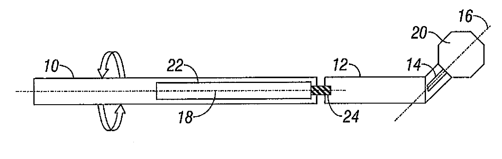
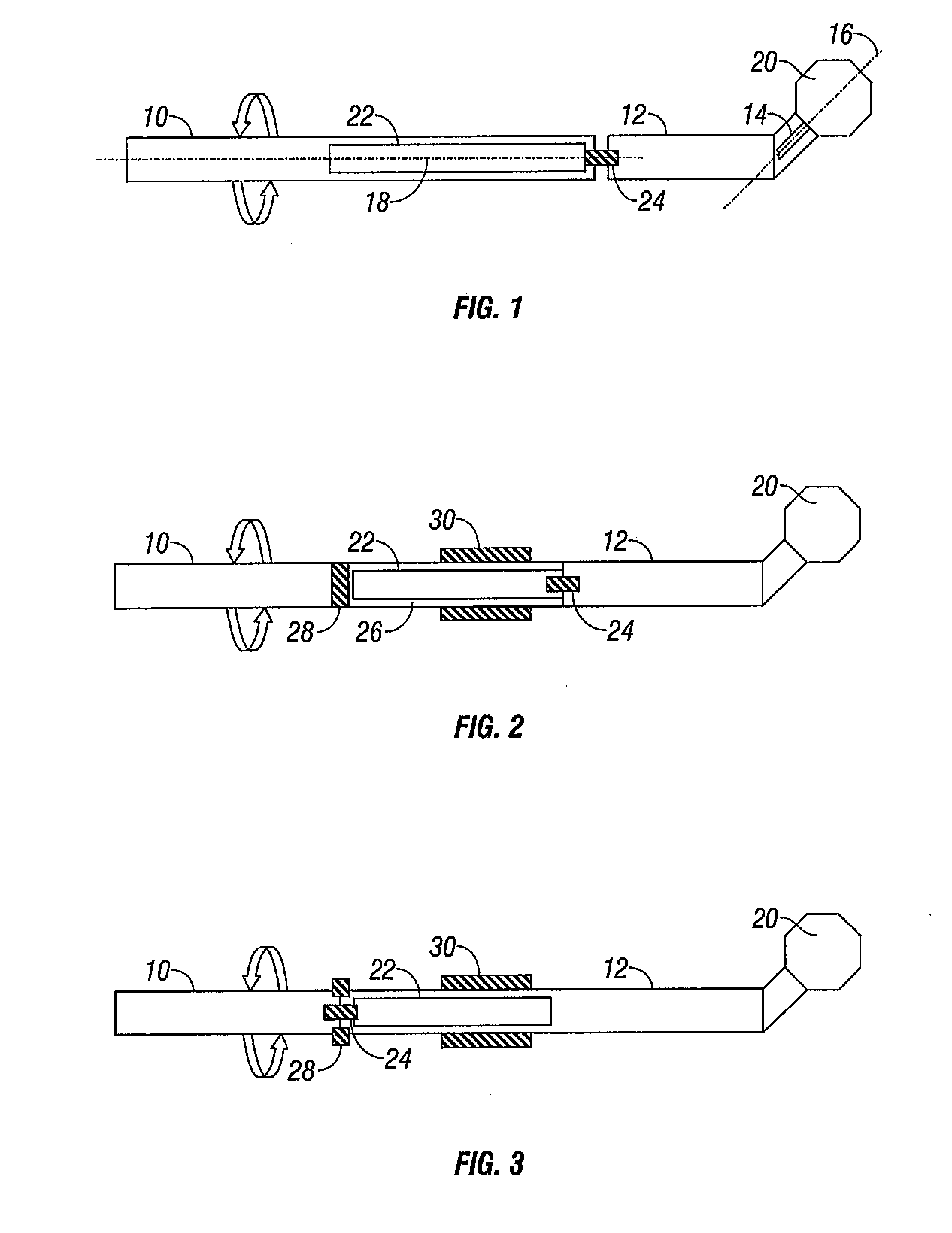
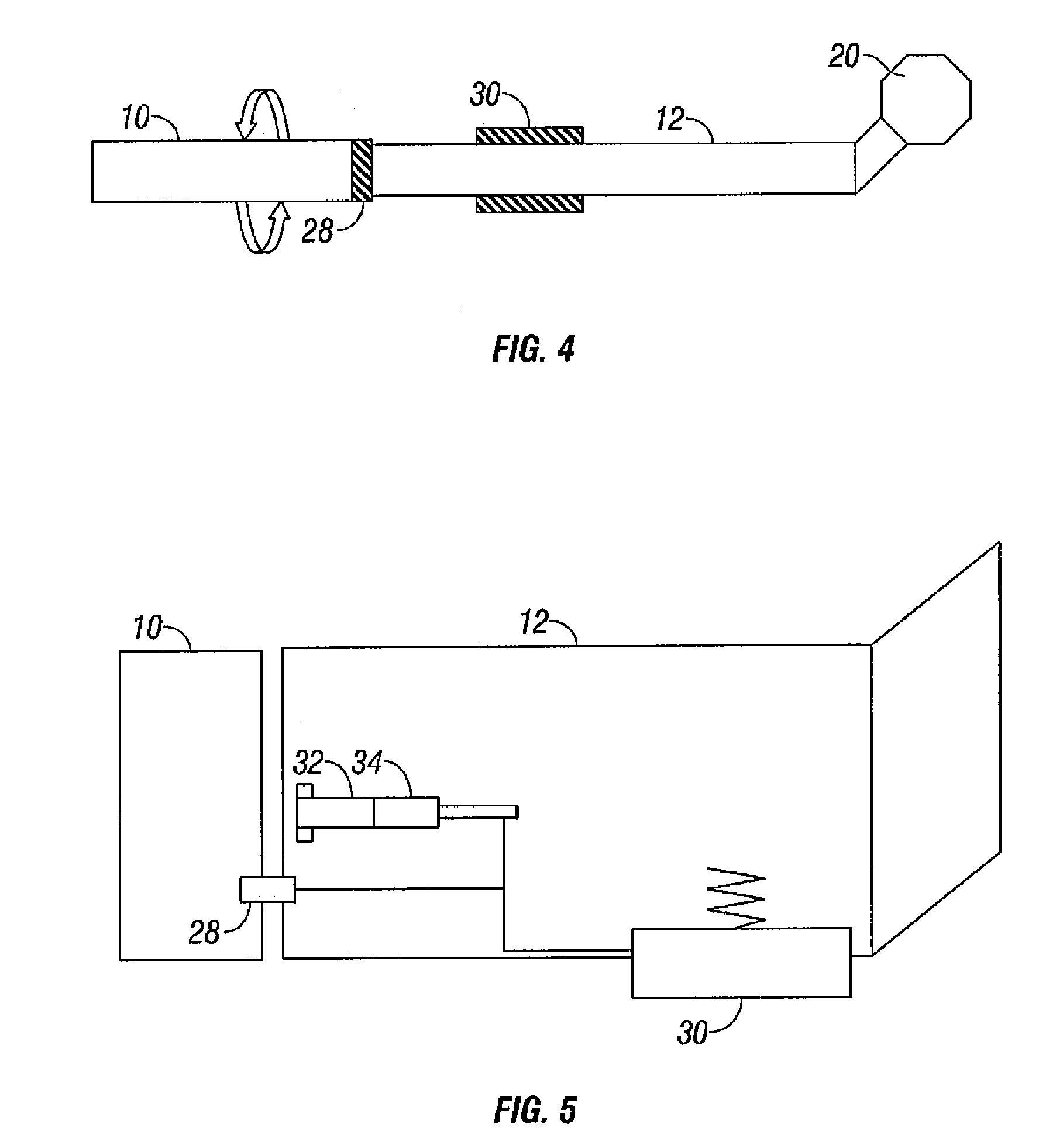
[0026] The steerable drilling system illustrated, diagrammatically, in FIG. 1 comprises a drill string 10 and a bent housing 12. The bent housing 12 contains a motor, for example a drilling fluid operated motor arranged to drive a drive shaft 14 for rotation about an axis 16 angled relative to the axis 18 of the end part of the drill string 10. A drill bit 20 is connected to the drive shaft of the motor such that operation of the motor causes rotation of the drill bit 20.

[0027] An orientating motor 22 is carried by the end of the drill string 10 adjacent the bent housing 12, the orientating motor 22 having an output shaft 24 connected to the bent housing 12 such that the orientating motor 22 controls the angular position of the bent housing 12 relative to the drill string 10.

[0028] In use, the drill string 10 is rotated in a conventional manner and a load is applied thereto to apply a weight-on-bit load to the bit 20. The bit drive motor located within the bent housing 12 is opera...


PUM


Abstract

A steerable drilling system comprising a drill string carrying a bent housing, the bent housing containing or having associated therewith a drive motor arranged to drive a drive shaft angled to an axis of part of the drill string adjacent the bent housing, and means permitting relative rotation between the drill string and the bent housing.

Description


Claims


Application Information

Patent Timeline
Owner SCHLUMBERGER TECH CORP
Why Eureka
Try Eureka