Separate optical device for directing light from an LED

a technology of led light and optical device, which is applied in the direction of optical elements, lighting and heating apparatus, instruments, etc., can solve the problems of significant non-uniformities between near-field and far-field distribution, inability to collect an f/1 acceptance angle of the led die, and inability to separate optical devices. to achieve the effect of reducing or eliminating the need for secondary optics

Inactive Publication Date: 2007-07-05
ILLUMITEX INC
View PDF99 Cites 65 Cited by
  • Summary
  • Abstract
  • Description
  • Claims
  • Application Information

AI Technical Summary

Benefits of technology

[0013] Embodiments of the present invention provide a separate optical device that provides technical advantages over the prior art by projecting light with a desired half-angle and intensity profile, while conserving brightness.
[0020] Yet another advantage provided by embodiments of the present invention is that light can be projected with a desired shape and intensity profile in both near and / or far field.

Problems solved by technology

However, there are several drawbacks to this design.
First, typical domes can only collect an f / 1 acceptance angle of the LED die.
Third, there can be significant non-uniformities between the near-field and far field distribution.
Lastly, the distribution itself is not spatially uniform.
Though this method does allow most if not all of the energy to get out, there are several significant drawbacks for practical applications.
Moreover, since most secondary optical systems only collect an f / 1 cone (a cone having a half angle of approximately 30 degrees or less), much of the light is lost.
Thirdly, since the dome is much larger than the LED die, the distribution is over a much larger area than necessary.
This adds complexity to the system and only addresses the problem of getting more light into a narrower cone angle.
These systems also do not address conservation of brightness of the source, creating a uniform pattern and maintaining the uniformity far field as well as near field.
Also, adding such a TIR lens increases the size and cost of a lighting package as much as tenfold, rendering this solution impractical for nearly all LED applications in electronics and portable devices.
While some reflective systems that re-image the LED from a dome can maintain the radiance (e.g., an ellipsoid where the LED is at one foci and the image is at the other foci), these systems are impractical for many applications.

Method used


Image

  • Separate optical device for directing light from an LED
  • Separate optical device for directing light from an LED
  • Separate optical device for directing light from an LED

Examples


Embodiment Construction

[0036] Preferred embodiments of the invention are illustrated in the FIGURES, like numerals being used to refer to like and corresponding parts of the various drawings.

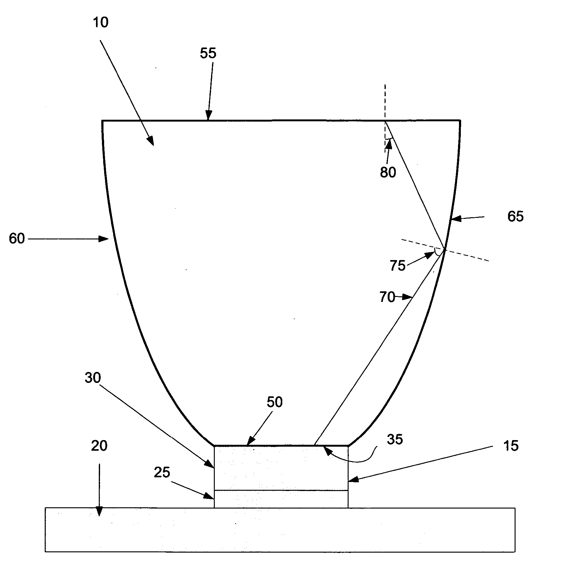
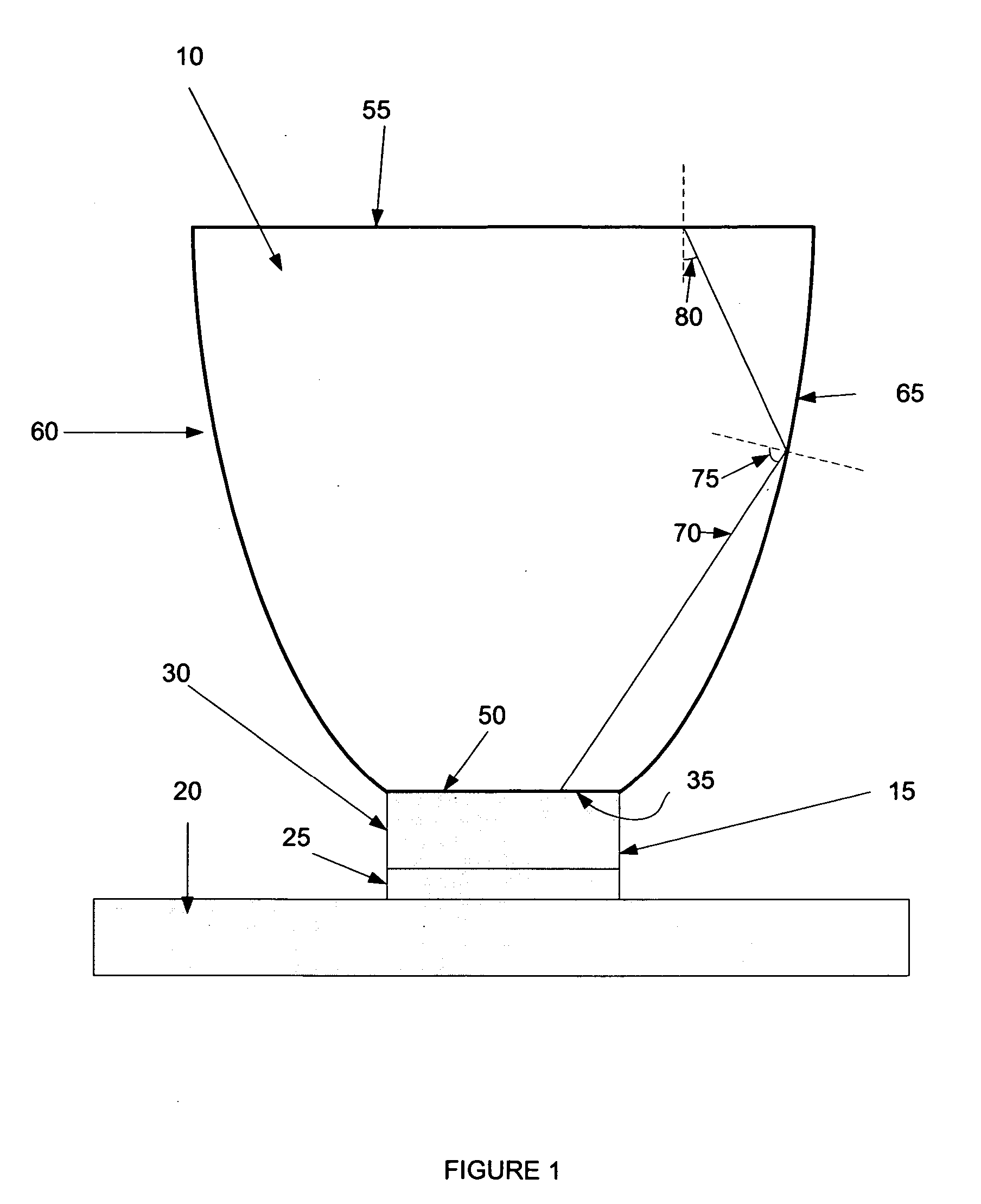
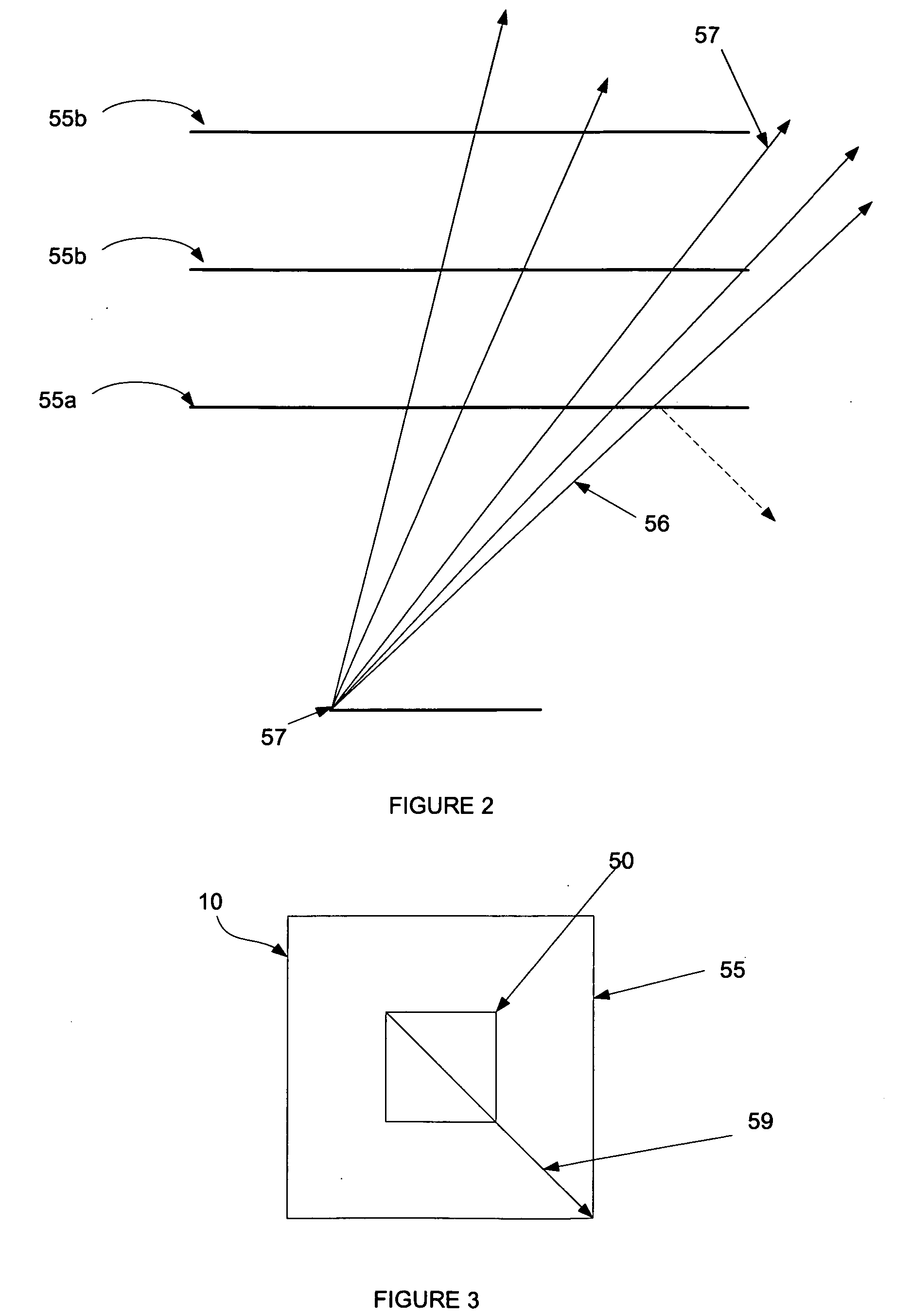
[0037] Embodiments of the present invention provide a separate optical device that is coupled to an LED to direct light from the LED to an exit interface of the separate optical device. Ideally, the separate optical device is configured so that all the light entering the separate optical device from the LED is transmitted out the exit interface. To this end, the exit interface can be sized to take into account principles of conservation of radiance. The exit interface may be the minimum size that allows all light entering the separate optical device from the LED to exit the exit interface, thereby combining the desire to conserve radiance with the desire to reduce size. Additionally, the sidewalls of the device may be shaped so that reflection or total internal reflection (“TIR”) causes light beams incident on the si...


PUM


Abstract

Embodiments of the present invention provide separate optical devices operable to couple to a separate LED, the separate optical device comprising an entrance surface to receive light from a separate LED when the separate optical device is coupled to the separate LED, an exit surface opposite from and a distance from the entrance surface and a set of sidewalls. The exit surface has at least a minimum area necessary to conserve brightness for a desired half-angle of light projected from the separate optical device. Furthermore, each sidewall is positioned and shaped so that at least a majority of rays having a straight transmission path from the entrance surface to that sidewall reflect to the exit surface with an angle of incidence at the exit surface at less than or equal to a critical angle at the exit surface.

Description

RELATED APPLICATIONS [0001] This application claims the benefit of priority under 35 U.S.C. 119(e) to U.S. Provisional Application No. 60 / 756,845, entitled “Optical Device”, to Duong et al., filed Jan. 5, 2006, which is hereby fully incorporated by reference herein.TECHNICAL FIELD OF THE INVENTION [0002] The present invention relates to separate optical devices. Even more particularly, embodiments of the present invention relate to devices and methods that increase the ability to harness light from a separate light emitting diode (“LED”). BACKGROUND [0003] Light emitting diodes (“LED”) are ubiquitous in electronics. They are used in digital displays, lighting systems, computers and televisions, cellular telephones and a variety of other devices. In an LED, as in a traditional diode, extra electrons move from an N-type semiconductor to electron holes in a P-type semiconductor. In an LED, however, photons are released to produce light during this process. For many applications it is d...

Claims


Application Information

Patent Timeline
Patent Type & Authority Applications(United States)
IPC IPC(8): H01L33/00H01L33/58H01L33/60
CPCH01L33/58H01L33/60F21V7/09G02B19/0061G02B19/0028H01L27/14629H01L27/14618H01L27/14627
Inventor DUONG, DUNG T.WINBERG, PAUL N.THOMAS, MATTHEW R.
Owner ILLUMITEX INC
Why Eureka
Try Eureka