
Light Regulatable Led Illumination Lamp

a technology of led lamps and dimmable lamps, which is applied in the direction of semiconductor lamps, electric discharge lamps, discharge tubes/lamp details, etc., can solve the problem of not having such a dimmable led lamp which can be applied

Active Publication Date: 2013-05-30
CHANGXING POTEK ELECTRONICS & TECH CO LTD
View PDF11 Cites 6 Cited by
  • Summary
  • Abstract
  • Description
  • Claims
  • Application Information

AI Technical Summary

Benefits of technology

This patent is about a new kind of LED lamp that can be dimmed through traditional dimmers, key switches, or even a wireless transmitter. It also has a feature to save brightness, which means it can be dimmed to a lower level while still keeping its brightness. Compared to existing LED lamps, this new lamp has the advantage of being smaller, lighter, and cooler. Dimmable LED lamps like this are becoming more popular in homes and buildings because they are more energy-efficient and can be controlled from different locations.

Problems solved by technology

However, there is no such a dimmable LED lamp which can be applied simultaneously with traditional dimmer, key switch and remote control to adjust the LED light.

Method used


Image

  • Light Regulatable Led Illumination Lamp
  • Light Regulatable Led Illumination Lamp
  • Light Regulatable Led Illumination Lamp

Examples


Embodiment Construction

[0023]To enable a further understanding of the innovative and technological content of the invention herein, refer to the detailed description of the invention and the accompanying drawings below:

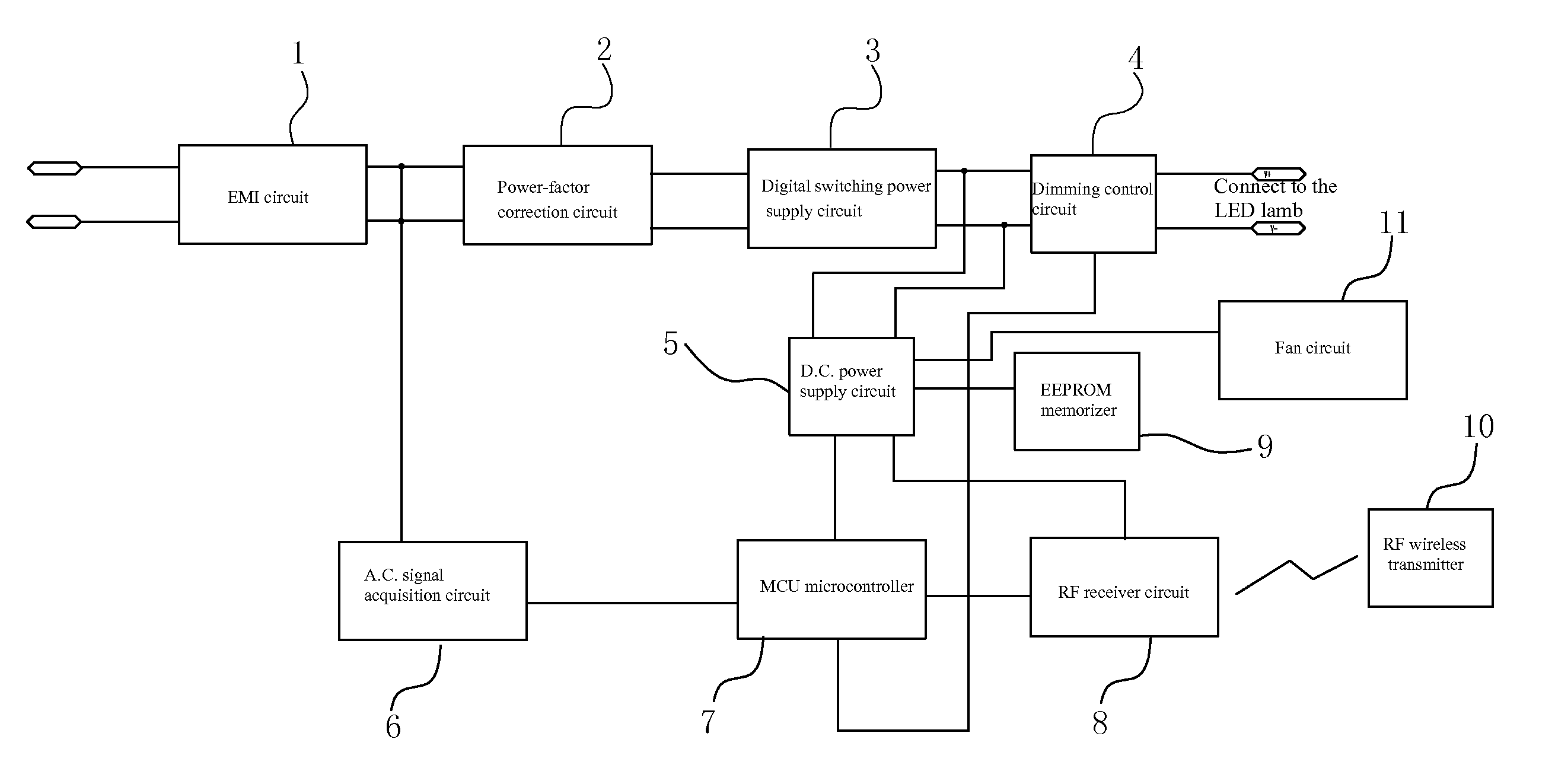
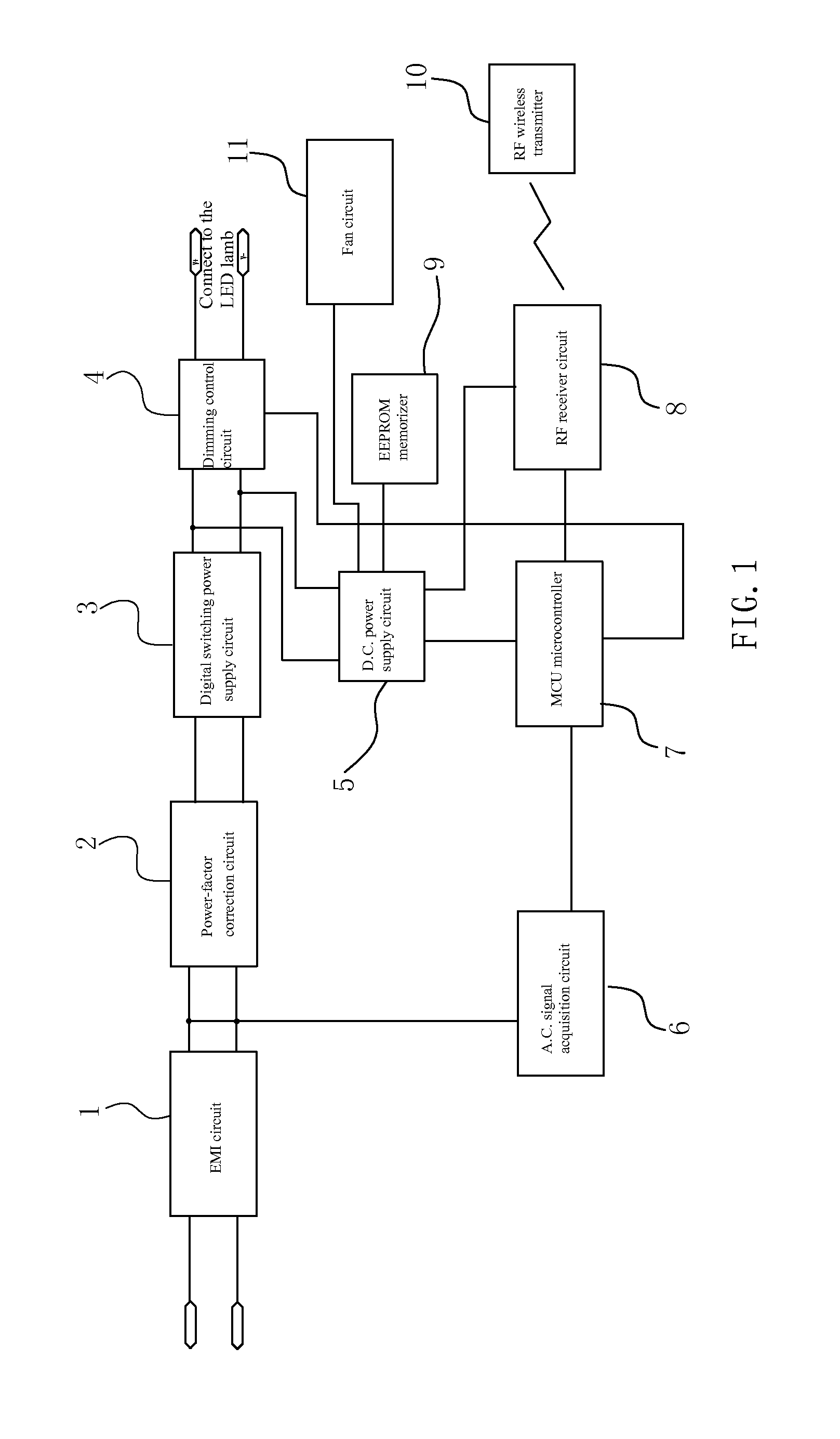
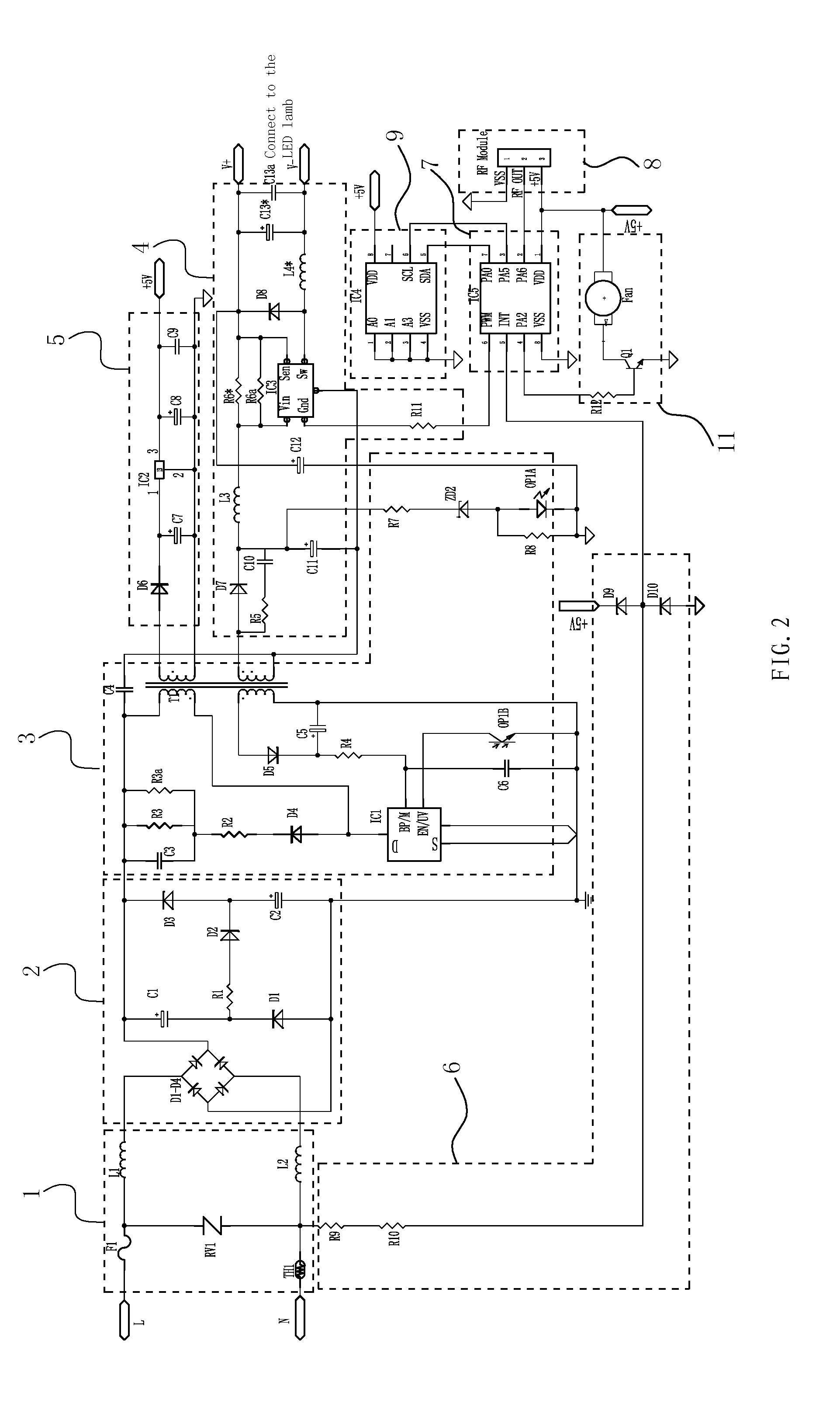
[0024]FIG. 1 and FIG. 2 show a preferred embodiment of the present invention. The dimmable LED lamp comprises a LED lamp, an EMI circuit resistance to electromagnetic interference, a power-factor correction circuit, a digital switching power supply circuit, a LED dimming control circuit, a D.C. power supply circuit, a MCU microcontroller, an EEPROM memorizer, an A.C. signal acquisition circuit, a fan circuit, a RF receiver circuit, and a RF wireless transmitter.

[0025]In the embodiment, the dimmable LED lamp is composed of a plurality of high-power LEDs which are connected in series, it has the advantages of high brightness, low power consumption, and long life, and it is becoming a mainstream choice for the customer in lighting industry.

[0026]The signal input of the EMI circuit 1 is connect...


PUM


Abstract

A dimming LED lamp having an LED light, an EMI circuit, a power-factor correction circuit, a digital switching power supply circuit, a dimming control circuit, a power supply circuit, a signal acquisition circuit, an MCU microcontroller, a RF wireless transmitter, a RF receiver circuit, an EEPROM memorizer, and a fan circuit. The brightness of the dimmable LED lamp can be dimmed through any conventional incandescent dimmers, or through any ordinary key switch, or through a wireless transmitter. The wireless transmitter can also remotely turn on the lamps or turn off the lamps, at the same time the LED lamp also has the function of brightness saving. The fan circuit uses air convection to cool the LED which has the advantages of aesthetically pleasing appearance, small size, light weight, low cost, long life, and good cooling effect.

Description

CROSS REFERENCE TO RELATED PATENT APPLICATION[0001]The present application is a PCT application No. PCT / CN2010 / 002164 entering the U.S.A. national stage and claiming the priority of the Chinese patent application No. 201020244529.5 filed on Jun. 28, 2010.FIELD OF THE INVENTION[0002]The present invention relates to a kind of a dimmable LED lamp.DESCRIPTION OF THE PRIOR ART[0003]The existing dimmable lamp can adjust the LED light directly through a traditional dimmer used in the incandescent lamp, or through a key switch, for instance, the technology in Chinese Patent CN201479444 (Patent No.: ZL200920192546.6); or by remote control, for instance, the technology in Chinese Patent CN201219323 (Patent No.: ZL 200820086672.9). However, there is no such a dimmable LED lamp which can be applied simultaneously with traditional dimmer, key switch and remote control to adjust the LED light.SUMMARY OF THE INVENTION[0004]It is an object of the present invention to provide a dimmable LED lamp whi...

Claims


Application Information

Patent Timeline
IPC IPC(8): H05B33/08H05B44/00H05B45/50
CPCH05B33/0809H05B37/0272H05B33/0851H05B33/0884H05B33/0833H05B45/10H05B45/50H05B47/19Y02B20/30H05B45/3725H05B45/36H05B45/325H05B45/355
Inventor QIN, BING
Owner CHANGXING POTEK ELECTRONICS & TECH CO LTD
Learn More