
Error corrected positioning stage

a positioning stage and error correction technology, applied in the field of manufacturing technology, can solve the problems of more machining centers that are capable of producing the required tolerances, difficult to find and more expensive to produce the positioning stage, and critical tolerances of the manufacturing process

Inactive Publication Date: 2007-07-05
CHITAYAT ANWAR K
View PDF21 Cites 12 Cited by
  • Summary
  • Abstract
  • Description
  • Claims
  • Application Information

AI Technical Summary

Benefits of technology

[0010] In the present invention, a movable positioning apparatus for positioning a work piece comprises one or more linear motors coupled to a base for supporting and moving one of a stage or work piece relative to the base in a longitudinal direction defined by a substantially longitudinal axis. A first detection device is coupled to the base and communicates with the stage or work piece for detecting a first d...

Problems solved by technology

Often, position tolerances for the manufacturing processes are critically tight.
One disadvantage of the strict tolerances is that fewer machining centers are capable of producing the required tolerances, and are thus more difficult to find and more expensive to produce the positioning stage.
Further disadvantages of current attempts to enhance accuracy of positioning apparatuses includes designing a positioning apparatus which becomes excessively large and heavy which adds to the costs of the apparatus from, for example, required building material, manufacture and machining, transporting, and location of use.
Therefore, increasing the size of a conventional positioning apparatus results in shortcomings and disadvantageous, and further, does not adequately scale up to accommodate larger size work pieces.
For larger work pieces, for example, those on the order of one to several square meters, a positioning apparatus of necessary precision and accuracy would be excessively massive, heavy and difficult to construct, and also difficult to assemble or calibrate particularly on-site.
Attempts to remedy the problems described above have heretofore been unsuccessful.
However, even if corrections are implemented based on the error map, the current machines generally are not capable of repetition, and for example, low cost machines generally tend to distort with time and consequently do not repeat.
Moreover, any change in temperature can change the position of the work piece due to the different coefficients of expansion of materials used, so that error mapping changes appreciably.
A further problem with error mapping occurs if excessive force such as a crash or electronic failure moves the rails or the mounting of the parts, in such a case, a new error map must be developed.
Another problem with error mapping pertains to the cost and the time in obtaining a master plate or other means for calibration of the apparatus in the field.

Method used


Image

  • Error corrected positioning stage
  • Error corrected positioning stage
  • Error corrected positioning stage

Examples


Embodiment Construction

.

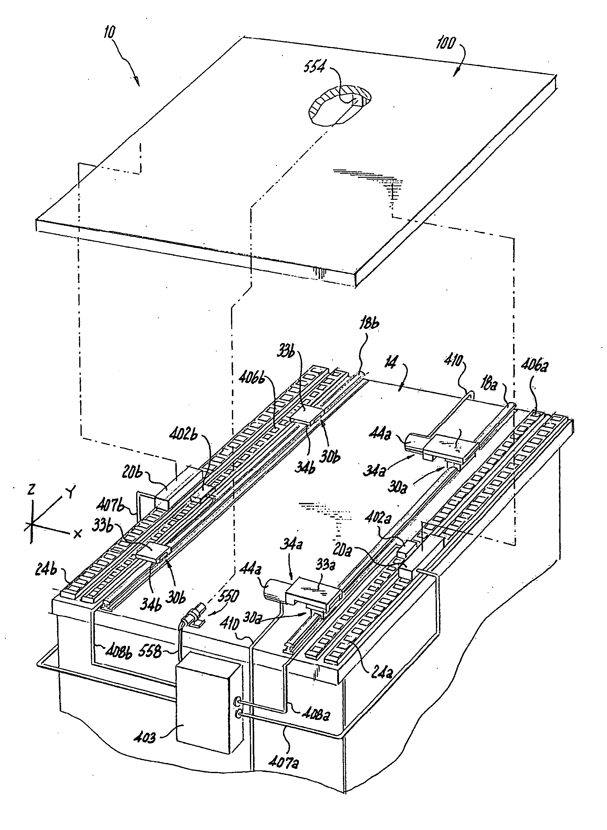
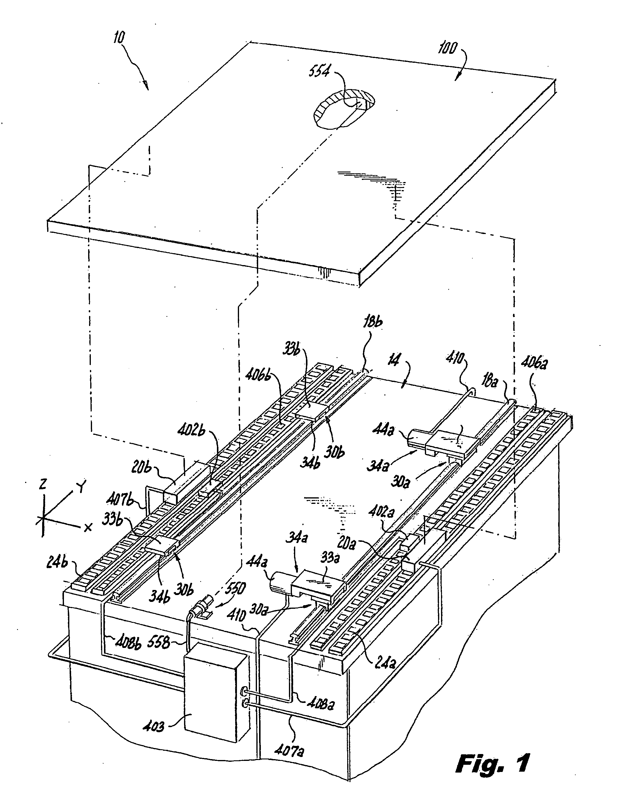
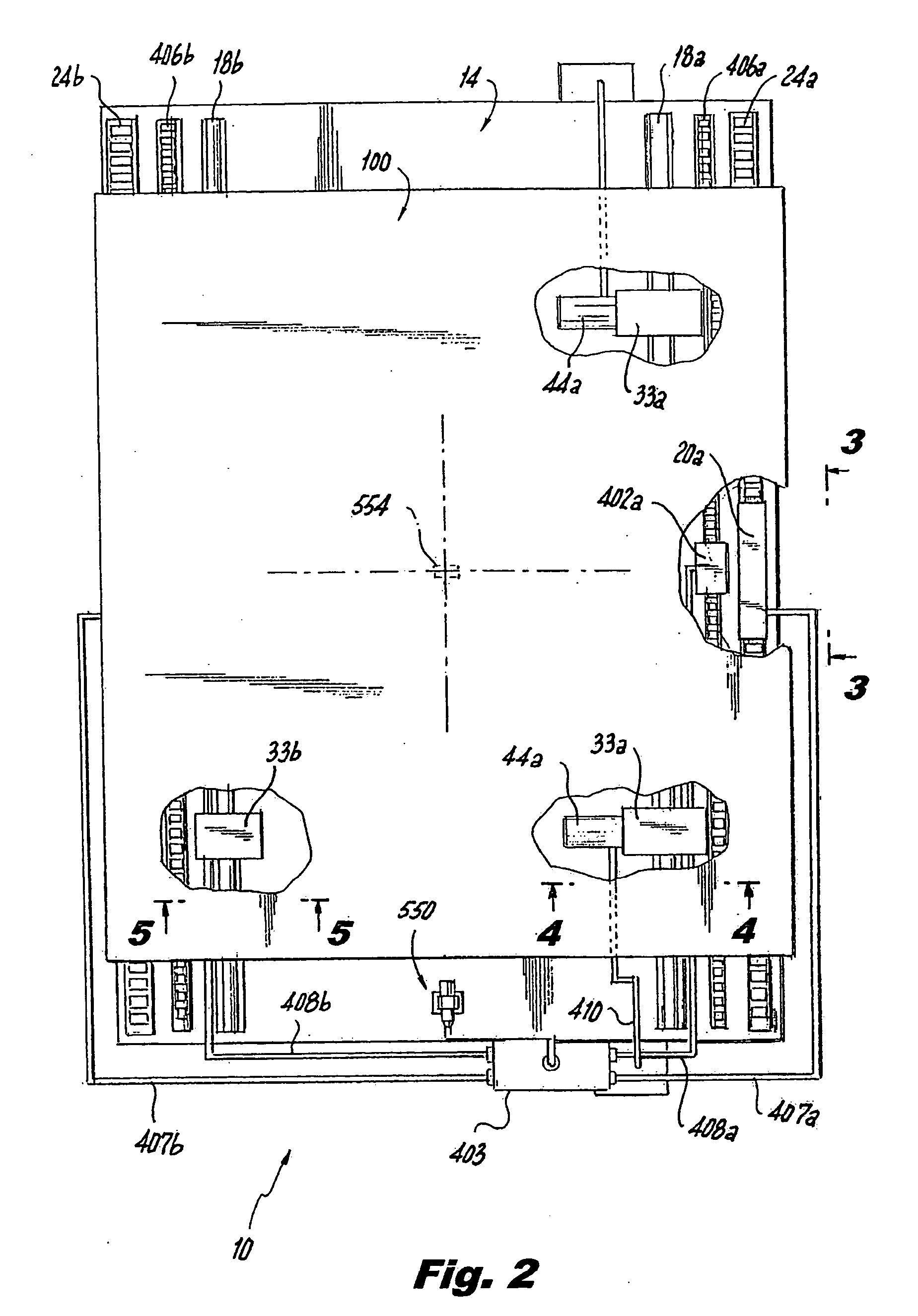
[0046] Referring to FIGS. 1 -3, a positioning apparatus 10, according to a first exemplary embodiment of the present invention comprises a base or undercarriage 14, and includes frame rails 18a and 18b extending in a “Y” direction in relation to a longitudinal axis (shown in FIG. 2). The frame rails 18a, 18b allow movement in the “Y” direction for carting or moving a movable stage 100. The frame rails 18a, 18b may also support a work piece directly. The base or undercarriage 14 provides a platform for other components of the positioning stage apparatus 10 which will be described below. Two linear motors 20a, 20b are mounted on top of magnet assemblies 24a, 24b, respectively, extending in the “Y” direction in relation to the longitudinal axis, and positioned on each side of the base 14 of the stage apparatus 10. It is possible that one linear motor, either 20a or 20b may suffice for a specific application, or either or both linear motors 20a, 20b may be replaced by a lead screw with...


PUM


Abstract

A movable positioning apparatus for positioning a work piece, which includes a base having linear motors attached thereto for supporting and moving a stage or work piece in a longitudinal direction relative to the base. The apparatus includes two linear encoders to measure rotation error by calculating the difference in measured positions. An alignment laser measures straightness errors. Two slides control yaw by moving in opposite directions, and the slides control straightness by moving in the same direction.

Description

CROSS-REFERENCE TO RELATED APPLICATION [0001] This application claims priority under 35 U.S.C. § 119(e) of U.S. Provisional Patent Application Ser. No. 60 / 766,018, filed 29 Dec. 2005, the complete disclosure of which is hereby incorporated by its reference for all purposes.BACKGROUND OF THE INVENTION [0002] 1. Field of Invention [0003] The present invention relates to a linear positioning stage apparatus for use in the field of manufacturing technology, and more specifically relates to a linear positioning stage apparatus with automatic positioning and correction for rotation straightness. [0004] 2. Description of Related Art [0005] In the manufacture of articles, particularly automated manufacture, it is expedient to position a raw material or work piece on a movable stage. The work piece is then positioned relative to a machine that performs some process on the work piece to advance or complete the manufacture. [0006] Often, position tolerances for the manufacturing processes are ...

Claims


Application Information

Patent Timeline
IPC IPC(8): B23Q1/25
CPCB23Q1/58B23Q1/267
Inventor CHITAYAT, ANWAR K.
Owner CHITAYAT ANWAR K
Learn More