Speed Crank Projection Lock Device for Trailer Landing Gear Assembly

a technology of projection lock and trailer landing gear, which is applied in the direction of lifting vehicle fittings, vehicle maintenance, transportation and packaging, etc., can solve the problem that the hand crank cannot move axially relative to the end of the input shaft, and achieve the effect of easy locking, easy unloading, and increasing manufacturing costs

Inactive Publication Date: 2007-07-05
BAXTER PROPERTIES
View PDF22 Cites 10 Cited by
  • Summary
  • Abstract
  • Description
  • Claims
  • Application Information

AI Technical Summary

Benefits of technology

[0015] The hand crank of the present invention overcomes the disadvantages associated with the prior art landing gear assembly hand cranks by providing a hand crank with a locking device that securely attaches the hand crank to the landing gear assembly input shaft in the operative position of the crank, and is quickly and easily unlocked from the input shaft enabling the hand crank to be pivoted to its stored position.
[0019] In the stored position of the hand crank beneath the input shaft, the coil spring pushes the plunger head into engagement with the side of the input shaft. As the hand crank is moved from its stored position beneath the input shaft toward its operative position relative to the input shaft, the plunger spring continues to push the plunger head into engagement with the shaft end. The shaft end slides across the plunger head surface as the hand crank is pivoted upwardly relative to the input shaft. As the hand crank approaches its operative position with the crank arm socket aligned with the shaft end, the shaft end approaches the hole in the plunger head surface. When the shaft end is aligned with the plunger head hole, the plunger spring pushes the plunger head toward the shaft end causing the shaft end to move into the plunger hole. This positively engages the crank arm to the landing gear assembly input shaft for rotation of the shaft on rotation of the crank arm. The coil spring biasing the plunger into engagement with the shaft end prevents the shaft end from becoming inadvertently disengaged from the crank arm as the crank arm is rotated. The pivot pin connection between the shaft end and the crank arm holes maintains the connection between the shaft and crank arm as the shaft is shifted axially by pulling on the crank arm. The coil spring pushing the plunger into engagement with the shaft end also provides a secure connection between the crank arm and the shaft, eliminating the wobbling feeling of the prior art hand crank and landing gear assembly shaft connection.
[0023] This second embodiment of the speed crank locking device functions in substantially the same manner as the first described embodiment. In the stored position of the hand crank beneath the input shaft, the coil spring pushes the plunger head into engagement with the side of the input shaft, holding the crank in the stored position. As the hand crank is moved from the stored position toward its operative position relative to the input shaft, the plunger spring continues to push the plunger head into engagement with the input shaft. The input shaft end slides across the plunger head as the hand crank is pivoted upwardly. As the hand crank approaches its operative position with the crank socket aligned with the input shaft end, the projecting post on the plunger end surface approaches the cavity in the input shaft end surface. When the post is aligned with the cavity, the plunger spring pushes the plunger toward the input shaft end, causing the plunger post to move into the shaft cavity. This positively engages the crank arm to the landing gear assembly input shaft for rotation of the shaft on rotation of the crank arm. The coil spring pushing the plunger into engagement with the input shaft end surface prevents the input shaft from being inadvertently disengaged from the crank arm as the crank arm is rotated. The pivot pin connection between the input shaft and the crank arm yoke holes maintains the connection between the shaft and the crank arm as the shaft is shifted axially by pulling and pushing on the crank arm. The coil spring pushing the plunger into engagement with the input shaft end also provides a secure connection between the crank arm and the shaft that holds the crank arm in its operative position, and eliminates the wobbling feeling of the prior art hand crank and landing gear assembly shaft connection.
[0026] All embodiments of the hand crank locking device of the invention require only minimal modifications to the component parts used in a conventional pivoting connection between a hand crank and a landing gear assembly input shaft. Both embodiments provide the benefits of a hand crank that is easily locked to the input shaft in its operative position, and is easily unlocked from the input shaft, without appreciably increasing the cost of manufacturing the hand crank and its connecting assembly to the input shaft.

Problems solved by technology

However, because the crank yoke arms do not have the elongated slots of the prior art hand crank, the hand crank cannot move axially relative to the end of the input shaft as does the prior art hand crank.

Method used


Image

  • Speed Crank Projection Lock Device for Trailer Landing Gear Assembly
  • Speed Crank Projection Lock Device for Trailer Landing Gear Assembly
  • Speed Crank Projection Lock Device for Trailer Landing Gear Assembly

Examples


Embodiment Construction

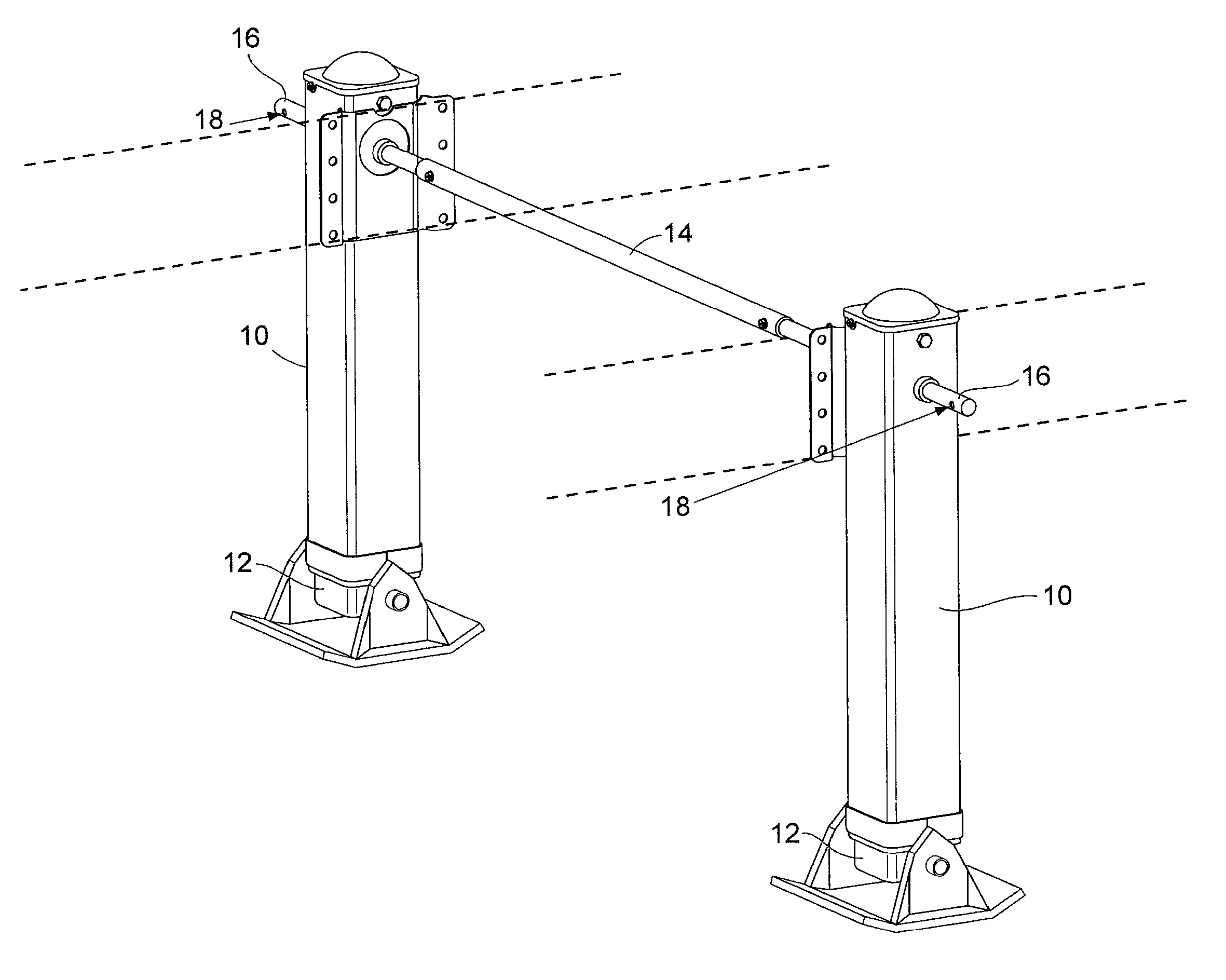
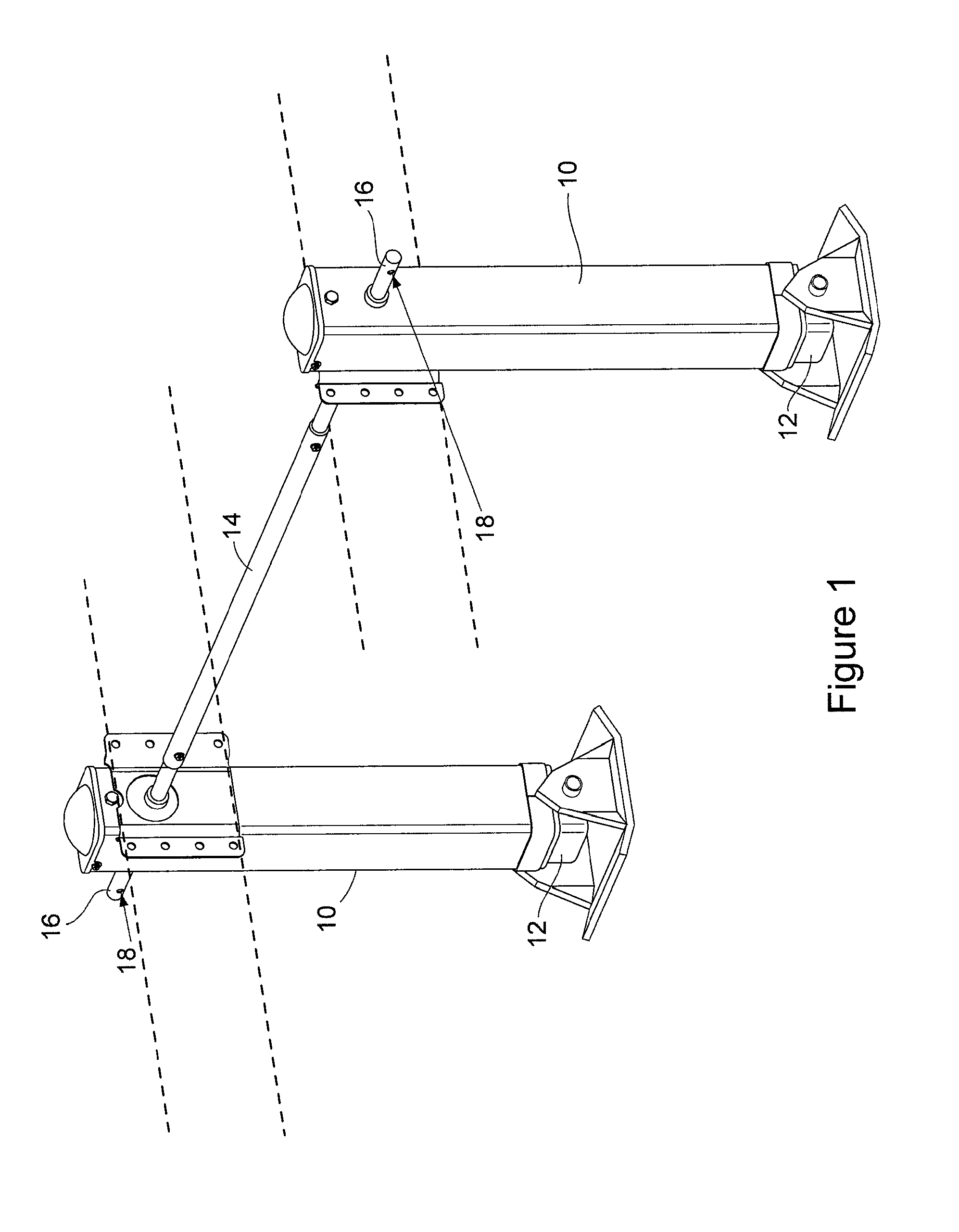
[0040]FIG. 1 shows one example of a manual drive apparatus that can be improved with the speed crank locking device of the present invention. It should be understood that the environment of FIG. 1 is only one example of an environment in which the speed crank locking device of the invention may be used. It is not intended that the speed crank locking device of the invention be limited to use with mechanisms such as that shown in FIG. 1.

[0041]FIG. 1 shows an example of a trailer landing gear assembly that is attached to frame members of a truck trailer represented by the dashed lines in FIG. 1. Landing gear assemblies of the type shown in FIG. 1 are known in the art, and therefore the assembly shall only be described generally herein. As described earlier, the typical landing gear assembly includes a pair of vertically oriented columns 10 positioned at opposite sides of the truck trailer. A vertical leg 12 is mounted inside each column 10. A gear mechanism (not shown) in each column...


PUM


Abstract

A speed crank locking device automatically secures a hand crank in its operative position to an input shaft of a gearing mechanism, with the locking device being easily disengaged to move the crank from its operative position to a stored position following rotation of the crank in the operation of the mechanism, the locked device also holding the crank in the stored position.

Description

[0001] This application is a continuation-in-part of patent application Ser. No. 11 / 076,674, which was filed Mar. 10, 2005, and is currently pending.BACKGROUND OF THE INVENTION [0002] (1) Field of the Invention [0003] The present invention pertains to a crank that is manually rotated to selectively lower and raise a landing gear assembly of a truck trailer. More specifically, the present invention pertains to a locking device that automatically secures the hand crank in its operative position relative to the landing gear assembly, where the locking device is easily disengaged to move the crank from its operative position to its stored position following the operation of the landing gear assembly. [0004] (2) Description of the Related Art [0005] Many of the different types of trailers that are towed by trucks are connected to the trucks by a releasable coupling such as a gooseneck coupling or a fifth wheel coupling. When the trailer is released from the truck and is no longer support...

Claims


Application Information

Patent Timeline
Patent Type & Authority Applications(United States)
IPC IPC(8): B60S9/02
CPCB60S9/08
Inventor BAXTER, DAVID A.BAXTER, BOBBY G.
Owner BAXTER PROPERTIES
Why Eureka
Try Eureka