
Non-graphical model dependencies in graphical modeling environments

a technology of graphical modeling environment and dependencies, applied in the field of graphical programming or modeling environment, can solve problems such as confusion in analysis of model execution or inspection of execution environment, and inability to achieve desired effects,

Active Publication Date: 2007-07-05
THE MATHWORKS INC
View PDF1 Cites 54 Cited by
  • Summary
  • Abstract
  • Description
  • Claims
  • Application Information

AI Technical Summary

Benefits of technology

[0005] The present invention provides graphical programming or modeling environments, such as a block diagram environment, in which dependencies that influence how a model executes are defined without altering the visual representation of the model. In the graphical modeling environment (or graphical programming environment), a user can create a model describing a system and execute (simulate) the model or generating code from the model. Using the present invention, the user can then augment the model with non-graphical dependencies that provide general execution goals or specific dependencies between blocks. The present invention enables the user to augment the graphical model with dependency constraints specifying how the model should execute. The constraints are coupled to the model and can be optionally displayed on the model in a debugging / analysis mode to provide further insight into how the model executes.
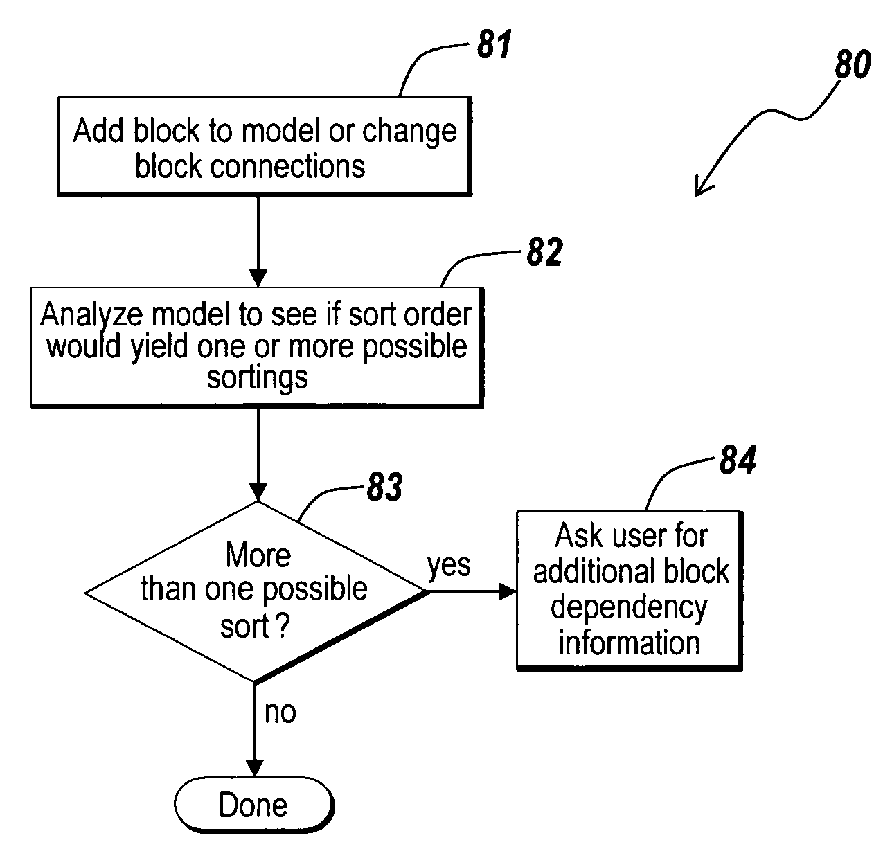
[0009] In an illustrative embodiment of the present invention, the user can augment the graphical model with dependencies selecting sorting criterion that influences model execution.
[0011] In another illustrative embodiment, the method, system and medium ensures inspection and verification of the execution environment by ensuring minimal alteration of the execution orderings by preserving existing block orderings when edits are made to the model.

Problems solved by technology

These variations can cause confusion in analysis of model execution or inspection of the execution environment.
These means are, however, cumbersome to use and fall short of achieving desired results in a short period of time.
In particular, the block sorting priorities fall short of enabling the user to specify execution dependencies that can be understood and managed at the model-wide level.
Moreover, this explicit specification of the extra dependencies hurts the readability of the diagram.

Method used


Image

  • Non-graphical model dependencies in graphical modeling environments
  • Non-graphical model dependencies in graphical modeling environments
  • Non-graphical model dependencies in graphical modeling environments

Examples


Embodiment Construction

[0037] Certain embodiments of the present invention are described below. It is, however, expressly noted that the present invention is not limited to these embodiments, but rather the intention is that additions and modifications to what is expressly described herein also are included within the scope of the invention. Moreover, it is to be understood that the features of the various embodiments described herein are not mutually exclusive and can exist in various combinations and permutations, even if such combinations or permutations are not made express herein, without departing from the spirit and scope of the invention.

[0038] The illustrative embodiment of the present invention provides a graphical programming or modeling environment in which a graphical program or model is simulated / executed or code is generated for the model. The terms “program / programming” and “model / modeling” will be used interchangeably in the description of the illustrative embodiment. In the description ...


PUM


Abstract

Graphical programming or modeling environments, such as a block diagram environment, are disclosed in which dependencies that influence how a model executes are defined without altering the visual representation of the model. In the graphical modeling or programming environment, users create a model that describes how the system is to execute. The users can then augment the model with non-graphical dependencies that provide general execution goals or specific dependencies between blocks. The user can augment the graphical model with dependency constraints specifying how the model should execute. The constraints are coupled to the model and can be optionally displayed on the model in a debugging / analysis mode to provide further insight into how the model executes.

Description

FIELD OF THE INVENTION [0001] The present invention relates to graphical programming or modeling environments, in particular to methods, systems and mediums for providing non-graphical model dependencies in the graphical programming or modeling environments. BACKGROUND OF THE INVENTION [0002] Various classes of graphical models describe computations that can be performed on application specific computational hardware, such as a computer, microcontroller, FPGA, and custom hardware. Classes of such graphical models may include time-based block diagrams such as those found within Simulink® version 6.3 (R14sp3) from The MathWorks, Inc. of Natick, Mass., state-based and flow diagrams such as those found within Stateflow® from The MathWorks, Inc. of Natick, Mass., physical models such as those found within SimMechanics from The MathWorks, Inc. of Natick Mass., entity flow network diagrams such as those found within SimEvents from The MathWorks, Inc. of Natick, Mass., discrete-event based ...

Claims


Application Information

Patent Timeline
Patent Type & Authority Applications(United States)
IPC IPC(8): G06F9/44
CPCG06F17/5009G06F8/10G06F8/35G06F30/20
Inventor CIOLFI, JOHN
Owner THE MATHWORKS INC
Learn More