Suction brush for vacuum cleaner

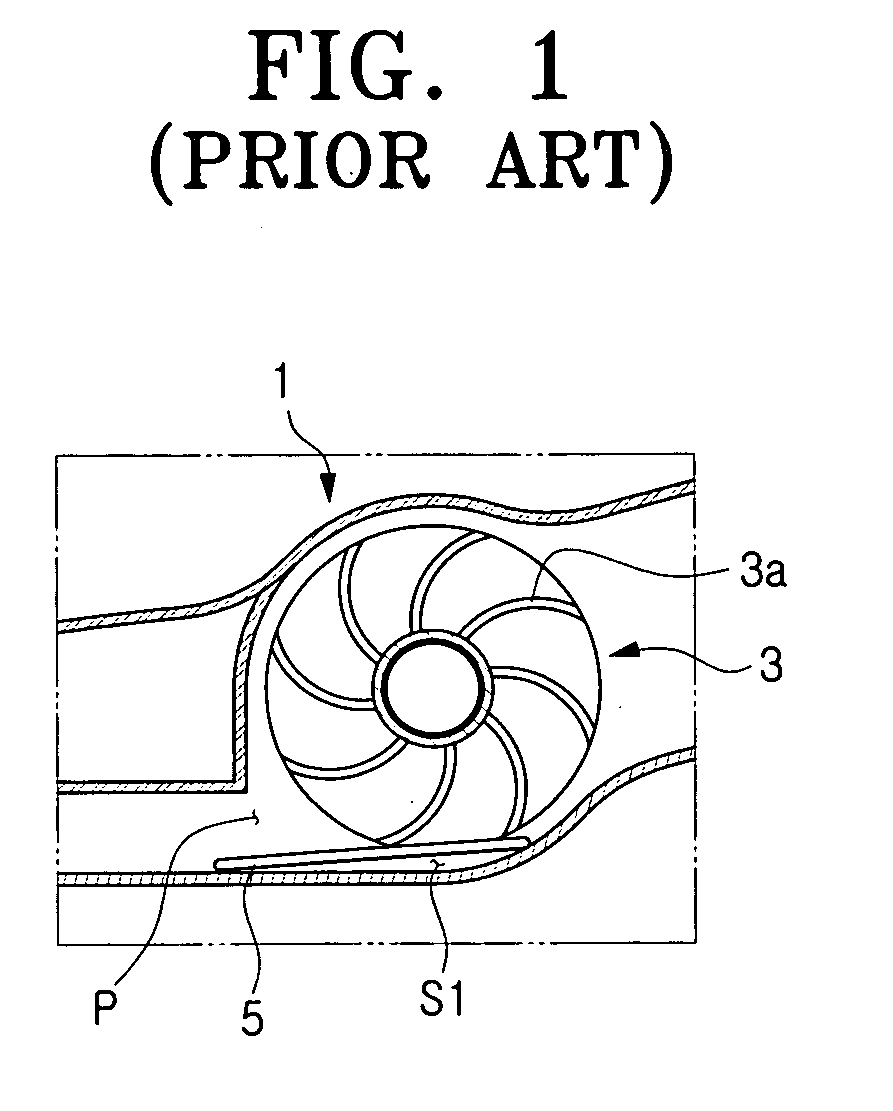
a vacuum cleaner and suction brush technology, which is applied in the field of suction brush for vacuum cleaners, can solve the problems of inconvenient cleaning with the conventional vacuum cleaner, inability to effectively remove foreign bodies adhered to the cleaning surface, and inability to wipe away the cleaning floor

Inactive Publication Date: 2007-07-12
SAMSUNG GWANGJU ELECTRONICS CO LTD
View PDF7 Cites 14 Cited by
  • Summary
  • Abstract
  • Description
  • Claims
  • Application Information

AI Technical Summary

Benefits of technology

[0011]The present invention has been developed in order to overcome the above drawbacks and other problems associated with the conventional arrangement. An aspect of the present invention is to provide a suction brush for a vacuum cleaner, which can prevent thin, long foreign bodies with relatively rigidity from entering a suction pathway.

Problems solved by technology

The vacuum cleaner can remove dust or / and contaminants scattered on a cleaning surface, but cannot effectively remove foreign bodies adhered on a cleaning surface and / or stains on a cleaning surface.
Thus, many users feel that it is inconvenient to clean with the conventional vacuum cleaner.
Therefore, users cannot wipe the cleaning floor away.
These problems are basically caused because there is no special structure around the suction port for preventing thin, long foreign bodies from entering the suction pathway.
On the other hand, because the conventional turbine fan is rotated by the indirect driving method using suction force by the suction motor, to increase the rotation speed and rotation torque of the cloth is limited compared to the direct driving method that a motor is directly connected to the cloth supporting part to rotate the cloth.
Therefore, when a cleaning surface is a little rough, the conventional suction brush cannot smoothly rotate the cloth so that a cleaning work is not effectively performed.

Method used


Image

  • Suction brush for vacuum cleaner
  • Suction brush for vacuum cleaner
  • Suction brush for vacuum cleaner

Examples


Embodiment Construction

[0035]Hereinafter, certain exemplary embodiments of the present invention will be described in detail with reference to the accompanying drawings.

[0036]The matters defined in the description, such as a detailed construction and elements thereof, are provided to assist in a comprehensive understanding of the invention. Thus, it is apparent that the present invention may be carried out without those defined matters. Also, well-known functions or constructions are omitted to provide a clear and concise description of exemplary embodiments of the present invention.

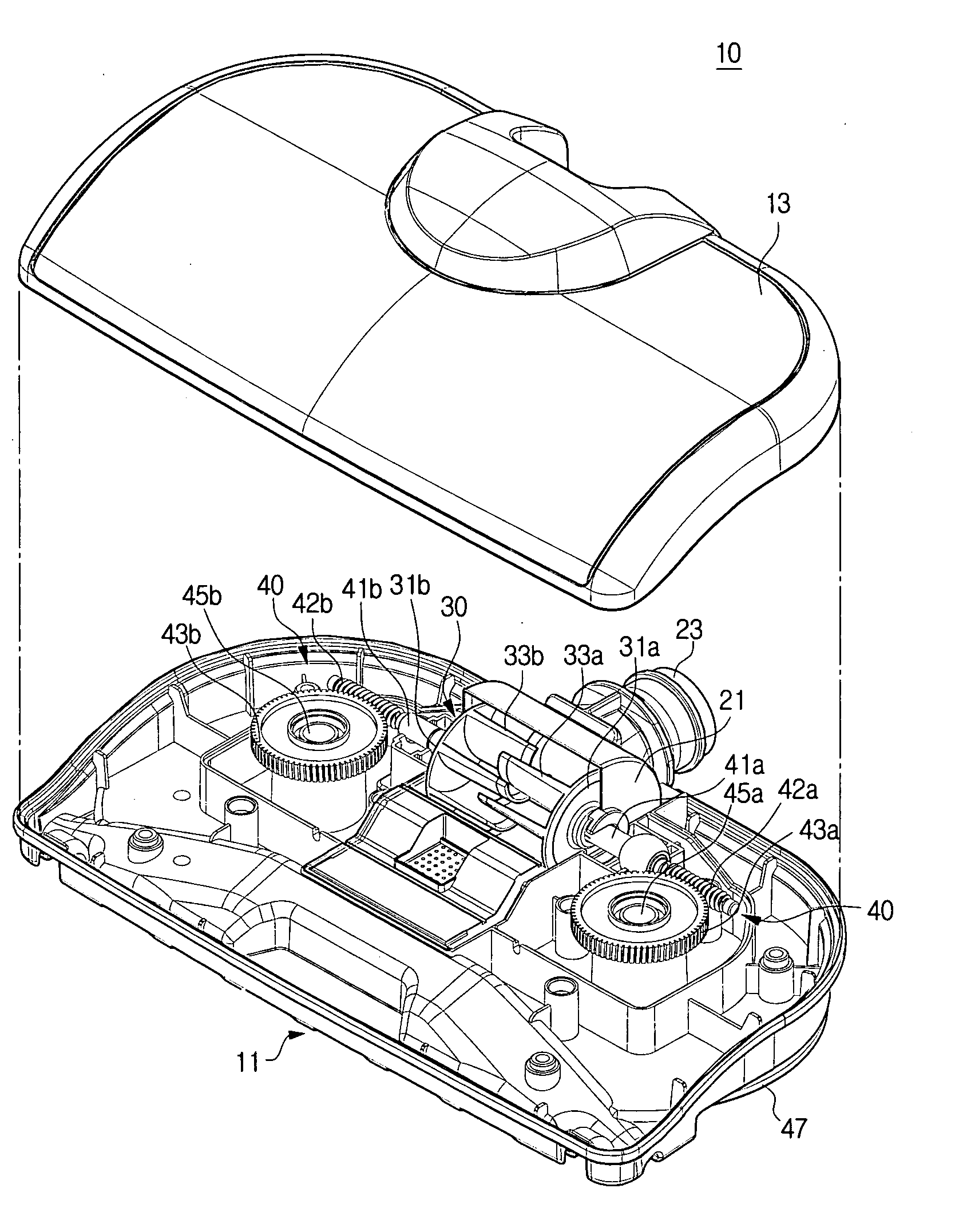
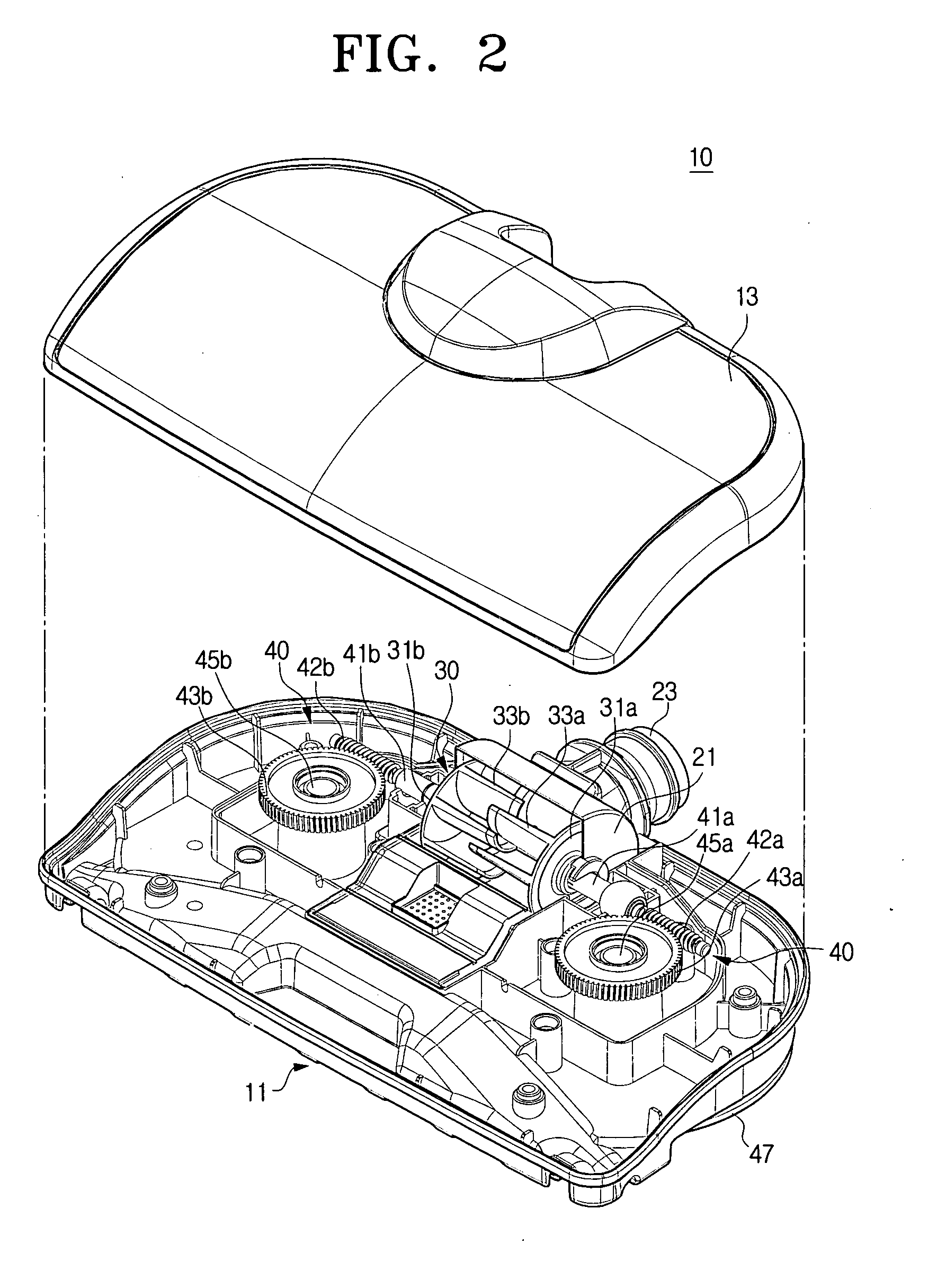
[0037]FIG. 2 is an exploded perspective view illustrating a suction brush for a vacuum cleaner according to an embodiment of the present invention, FIG. 3 is a partially cutaway perspective view illustrating a suction brush for a vacuum cleaner according to an embodiment of the present invention, FIG. 4 is a perspective view illustrating a turbine fan of FIG. 2, FIG. 5 is a partial perspective view illustrating an under side o...


PUM


Abstract

The present invention relates to a suction brush for a vacuum cleaner. The suction brush includes a cleaning member for cleaning a cleaning surface, a suction port and a dust guiding groove for guiding contaminants-laden air to the suction port to be formed at a bottom surface of the suction brush, and a turbine fan driven by suction force of a suction motor for rotating the cleaning member. The suction brush comprises a catching part disposed apart from the suction port in a place corresponding to the suction port inside the dust guiding groove for reducing a space around the suction port, wherein the catching part prevents rigid, thin, and long foreign bodies from entering the suction pathway.

Description

BACKGROUND OF THE INVENTION[0001]1. Field of the Invention[0002]The present invention relates to a suction brush for a vacuum cleaner. More particularly, the present invention relates to a suction brush for a vacuum cleaner with cloths.[0003]2. Description of the Related Art[0004]Generally, a vacuum cleaner is an apparatus for sucking dust or contaminants on a cleaning surface using suction force generated by a suction motor when a suction brush is moved on the cleaning surface.[0005]The vacuum cleaner can remove dust or / and contaminants scattered on a cleaning surface, but cannot effectively remove foreign bodies adhered on a cleaning surface and / or stains on a cleaning surface. At this time, after removing dust on a floor of a room using the vacuum cleaner, users should scrub the floor using a cloth in order to remove adhered foreign bodies or stains remaining on the cleaning surface. Thus, many users feel that it is inconvenient to clean with the conventional vacuum cleaner.[0006...

Claims


Application Information

Patent Timeline
Patent Type & Authority Applications(United States)
IPC IPC(8): A47L5/10
CPCA47L9/02A47L9/04A47L9/0472A47L9/0433A47L9/0416H02K33/16H02K33/02
Inventor OH, JANG-KEUNHAN, JUNG-GYUNLIM, SOON-TACK
Owner SAMSUNG GWANGJU ELECTRONICS CO LTD
Why Eureka
Try Eureka