Plug bypass valves and heat exchangers

Inactive Publication Date: 2007-07-12
DANA CANADA CORP
View PDF33 Cites 18 Cited by
  • Summary
  • Abstract
  • Description
  • Claims
  • Application Information

AI Technical Summary

Problems solved by technology

However, when the transmission is cold, such as at start-up conditions, the transmission oil is very viscous and does not flow easily through the heat exchanger, if at all.
In such cases, the transmission can be starved of fluid and this may cause damage to the transmission or at least erratic performance.
Damage can also be caused to the transmission if the quantity of fluid returned is adequate, but is over-cooled by the heat exchanger due to low ambient temperatures.
In this case, water may accumulate in the transmission fluid as a result of condensation (which normally would be vaporized at higher temperatures) and this may cause corrosion damage or transmission fluid degradation.
While this approach works satisfactorily, the heat exchanger and bypass valve assembly becomes quite large and includes fluid inlet and outlet tubing that may not otherwise be required.

Method used


Image

  • Plug bypass valves and heat exchangers
  • Plug bypass valves and heat exchangers
  • Plug bypass valves and heat exchangers

Examples


Embodiment Construction

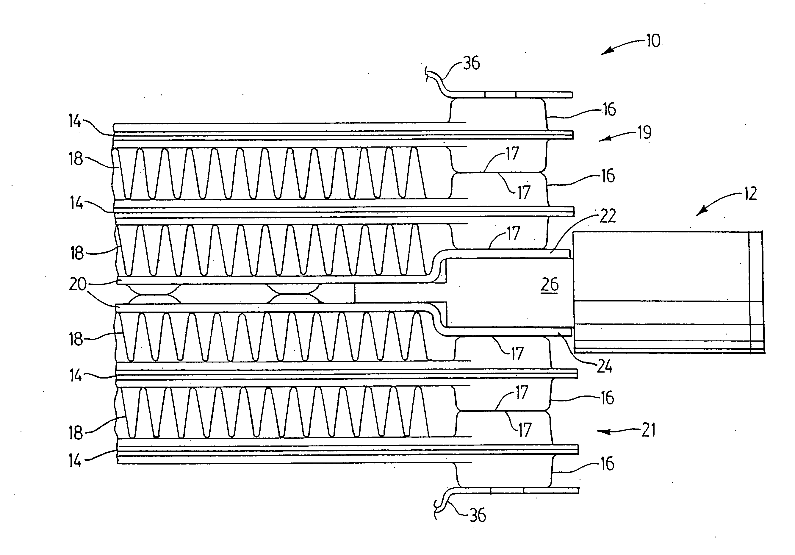
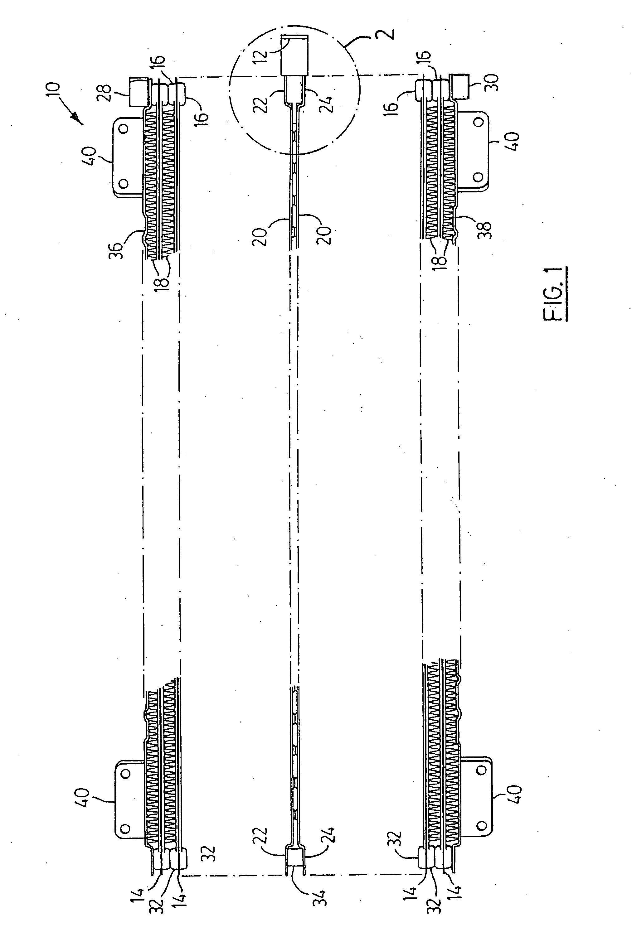
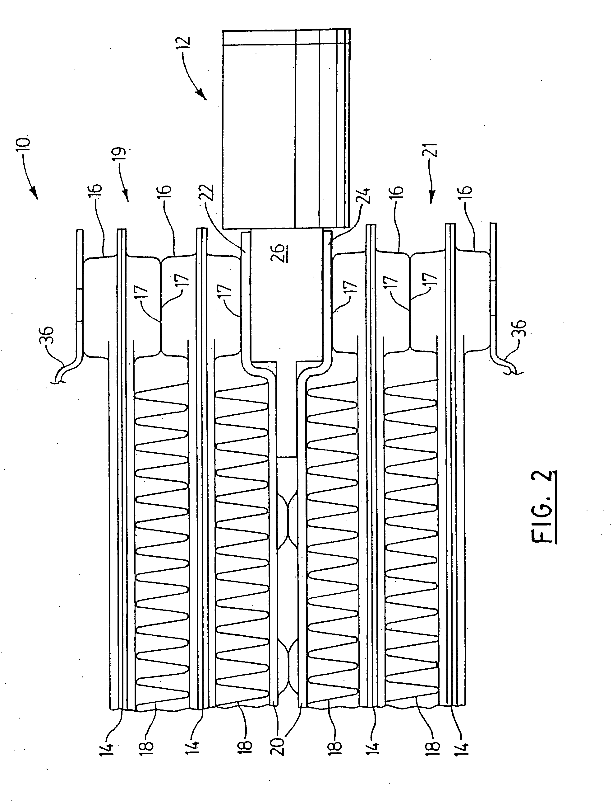
[0016] Referring firstly to FIGS. 1 and 2, a heat exchanger is generally indicated by reference in 10, and a preferred embodiment of a bypass valve according to the present invention is generally indicated by reference numeral 12. Heat exchanger 10 is formed of a plurality of parallel, spaced-apart, tubular members 14 preferably with enlarged distal end portions 16 that have adjacent wall portions 17 defining flow openings (not shown) in communication. Tubular members 14 are preferably formed of mating plate pairs with transversely protruding cupped end portions to form these enlarged end portions 16 that also together form flow manifolds 19 and 21. However, tubular members 14 could be formed of tubes with separate joined enlarged end portions 16, if desired. Alternatively, tubular members of uniform width or thickness could be used, in which case tubular spacers could be used between the tube ends in place of enlarged distal end portions 16. If it is not necessary to space tubular ...


PUM


Abstract

Bypass valves and heat exchangers employing same are shown where the bypass valves cause the flow through the heat exchangers to be short-circuited under certain temperature conditions. The heat exchangers are formed of stacked plate pairs or tubes having enlarged communicating distal end portions forming inlet and outlet manifolds. The bypass valves can be plugged in where desired between the enlarged distal end portions to produce bypass flow between the inlet and outlet manifolds. The bypass valves include a housing which can be brazed in place during brazing of the heat exchanger. The housing has inlet and outlet openings in communication with the respective inlet and outlet manifolds for bypass flow therebetween. A removable temperature responsive actuator is located in the housing for blocking and unblocking the bypass flow through the valve.

Description

[0001] This application is a continuation of U.S. application Ser. No. 09 / 918,082 filed Jul. 30, 2001, the entire disclosure of which is incorporated herein by reference, which itself claims priority to Canadian Application No. 2,354,217 filed on Jul. 26, 2001.BACKGROUND OF THE INVENTION [0002] This invention relates to heat exchangers, and in particular, to bypass valves for bypassing or short-circuiting flow from the heat exchanger inlet to the heat exchanger outlet under conditions where the heat transfer function of the heat exchanger is not required or is only intermittently required. [0003] In certain applications, such as in the automotive industry, heat exchangers are used to cool or heat certain fluids, such as engine oil or transmission fluid or oil. In the case of transmission fluid, for instance, a heat exchanger is usually used to cool the transmission fluid. The heat exchanger is usually located remote from the transmission and receives hot transmission fluid from the ...

Claims


Application Information

Patent Timeline
IPC IPC(8): F28F27/02G05D23/00F01M5/00F01P7/14F01P7/16F28D1/03G05D23/02
CPCF01M5/00F01M5/005F01P2007/146F01P2007/168F01P2060/04G05D23/022F28D1/0333F28D1/05358F28D2021/0089F28F27/02F28F2250/06F01P2060/045
Inventor PINEO, GREGORY MERLECHEADLE, BRIAN EDWARD
Owner DANA CANADA CORP
Why Eureka
Try Eureka