Hinged Polyaxial Screw and methods of use

a polyaxial screw and screw body technology, applied in the field of polyaxial screws, can solve the problems of significant morbidity, instability of the spine, abnormal motion between adjacent vertebrae,

Inactive Publication Date: 2007-07-12
PARADIGM SPINE LLC
View PDF31 Cites 264 Cited by
  • Summary
  • Abstract
  • Description
  • Claims
  • Application Information

AI Technical Summary

Problems solved by technology

Diseases of the spine cause significant morbidity.
Such abnormalities can cause instability to the spine, vertebral misalignment, and abnormal motion between adjacent vertebrae.
More severe disease may result in wear to the vertebral bony surfaces or cause nerve compression, which may ultimately produce severe pain.
Further, spinal conditions are often chronic and progressive problems.
For some patients this may require chron

Method used


Image

  • Hinged Polyaxial Screw and methods of use
  • Hinged Polyaxial Screw and methods of use
  • Hinged Polyaxial Screw and methods of use

Examples


Embodiment Construction

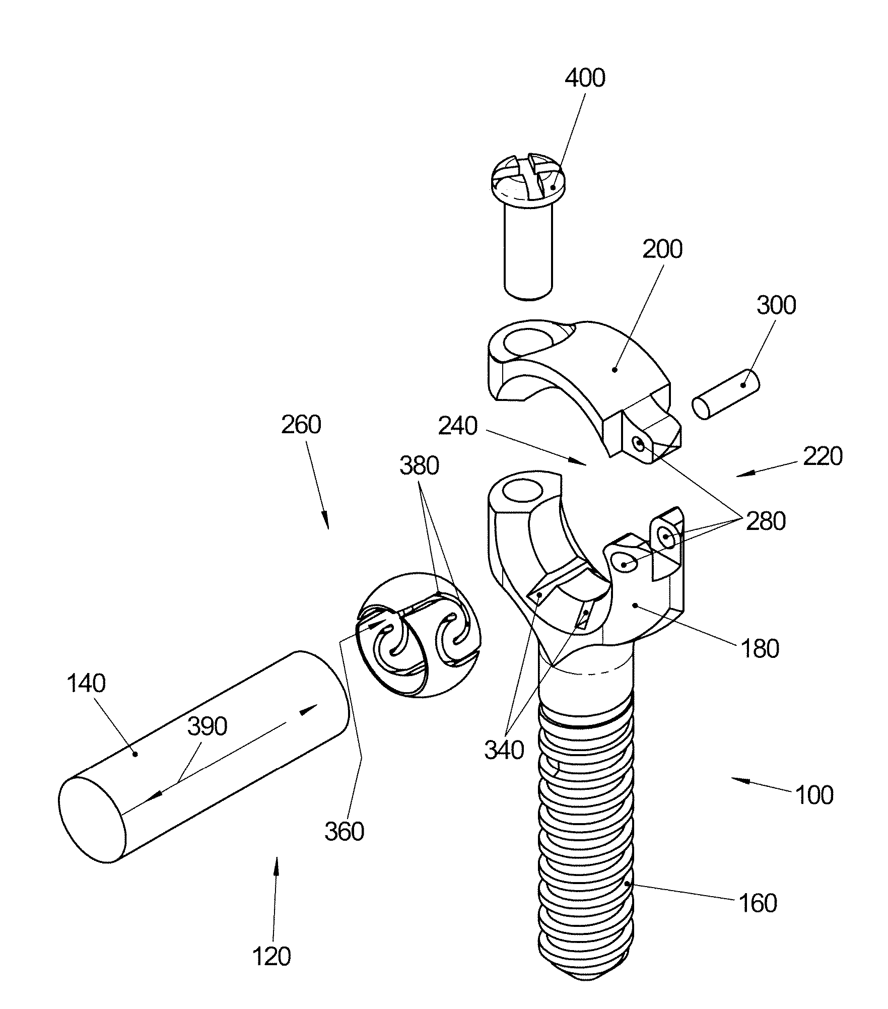
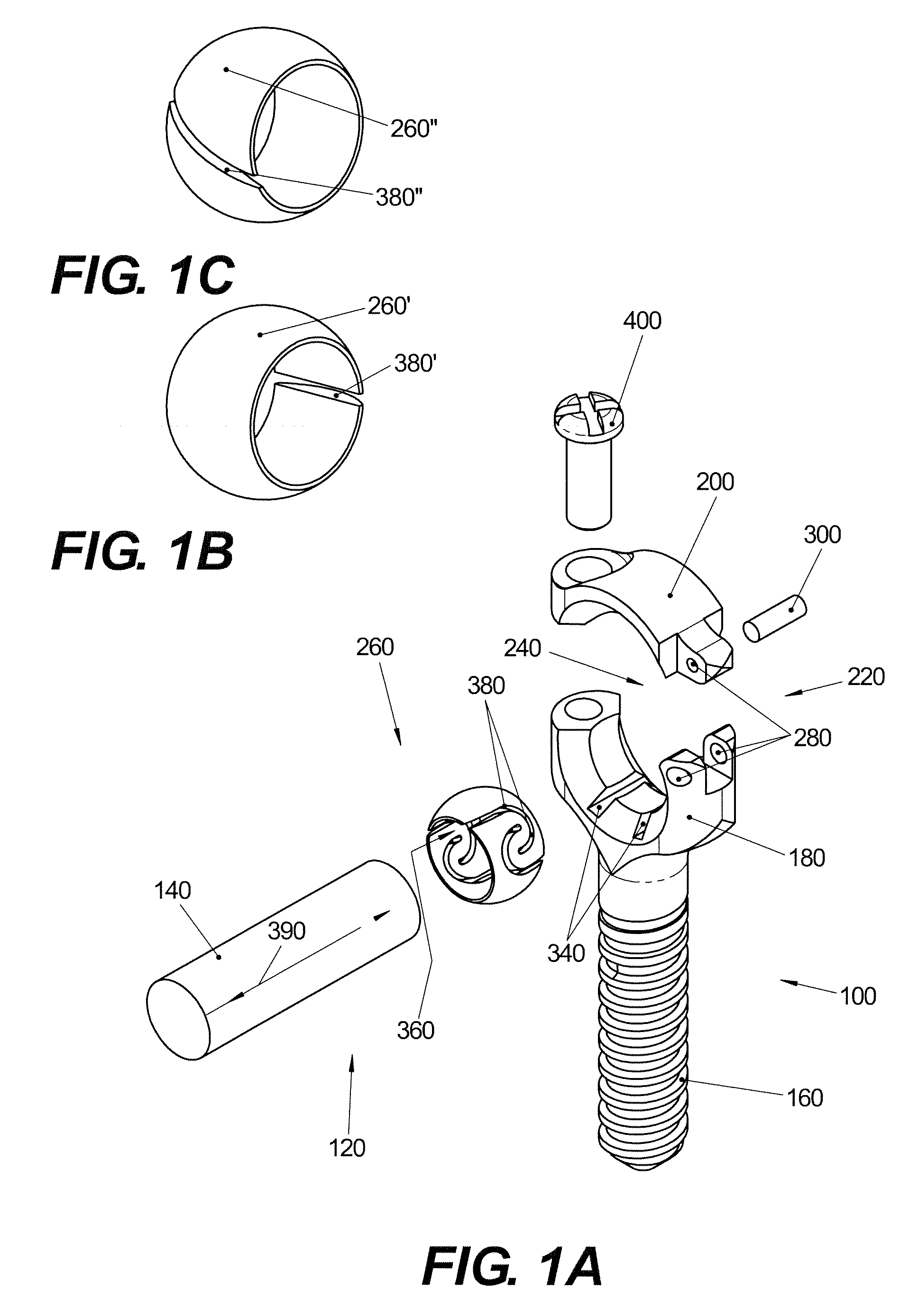
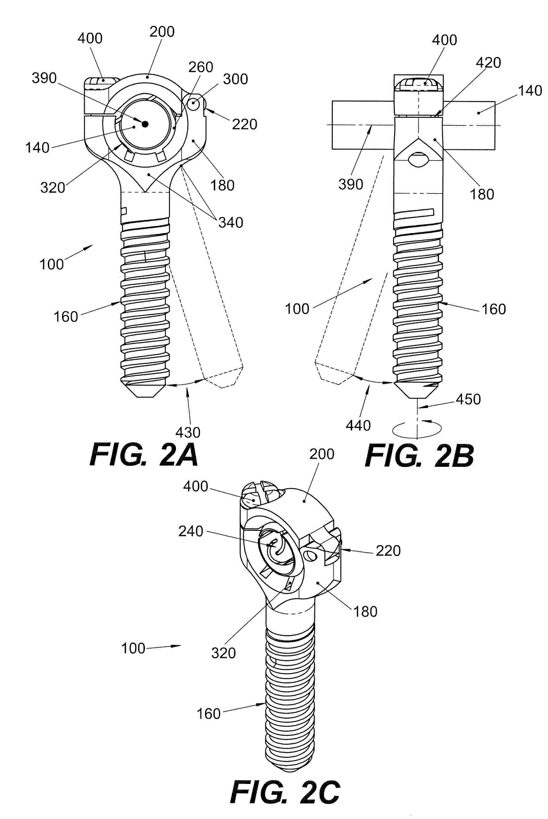
[0019]FIG. 1A illustrates the component parts of a bone-anchoring device 100 and rod-connection system 120, according to an exemplary embodiment. The bone-anchoring device 100 may include a threaded shaft 160, which may be configured to securely engage one or more bony structures. The bone-anchoring device 100 may further include a head portion 180 securely attached to the shaft 160 and a cap 200. The cap 200 may form a hinged connection 220 with the head portion 180, and collectively, the head portion 180 and the cap 200 may form part of a substantially spherical cavity 240. A substantially spherical connector 260 may be provided as part of the rod-connection system 120 to facilitate secure connection of the bone-anchoring device 100 and an implant such as a stabilization rod 140, as shown in FIGS. 2A and 2B. The connector 260 may be configured to be disposed within the cavity 240 during use.

[0020] As shown, the stabilization rod 140 comprises a cylindrical rod. However, it is und...


PUM


Abstract

A bone-anchoring device is provided. The device may include a substantially rigid shaft having a threaded portion configured to engage bone. The bone-anchoring device may further include a head portion securely attached to the shaft and a cap portion having a hinged connection with the head portion. A substantially spherical cavity may be formed between the head portion and the cap portion.

Description

FIELD OF THE INVENTION [0001] The present invention relates to devices and methods for anchoring surgical implants to bony tissue. Specifically, the present invention pertains to polyaxial screws, which may be configured for use with bone-stabilization devices such as implantable rod stabilization systems. BACKGROUND OF THE INVENTION [0002] Diseases of the spine cause significant morbidity. These diseases include abnormalities of the vertebrae, the intervertebral discs, the facet joints, and connective tissue around the spine. These abnormalities can be caused by a number of factors, including mechanical injury or degenerative disc disease. Such abnormalities can cause instability to the spine, vertebral misalignment, and abnormal motion between adjacent vertebrae. More severe disease may result in wear to the vertebral bony surfaces or cause nerve compression, which may ultimately produce severe pain. Further, spinal conditions are often chronic and progressive problems. [0003] The...

Claims


Application Information

Patent Timeline
IPC IPC(8): A61F2/30
CPCA61B17/7032A61B17/8605A61B17/704A61B17/70A61B17/86
Inventor LOWERY, GARY L.TRAUTWEIN, FRANK T.
Owner PARADIGM SPINE LLC
Why Eureka
Try Eureka