Recording Trace Messages of Processes of a Network Component

a network component and trace message technology, applied in the field of multi-process systems, can solve the problems that newer telecommunications architectures create challenges and opportunities for telecommunication networks, and achieve the effect of substantially reducing the disadvantages and eliminating the problems of multiple process systems

Inactive Publication Date: 2007-07-19
CISCO TECH INC
View PDF25 Cites 14 Cited by
  • Summary
  • Abstract
  • Description
  • Claims
  • Application Information

AI Technical Summary

Benefits of technology

[0006] In accordance with the present invention, the disadvantages and problems associated with multiple process systems have been substantially reduced or eliminated.
[0008] Examples of the present invention may include none, some, or all of the following technical advantages. A technical advantage of one example is that trace functions may be provided for a multiple process system or multiple thread system, for example, a telecommunication network, where there may be a number of processes that are single-threaded or multi-threaded. The embodiment may provide a centralized, time ordered trace facility, where trace messages output by the multiple threads of multiple processes may be collected together and placed in time sequence with minimal performance impact.
[0010] A technical advantage of another example is that a process thread of a process may be assigned a buffer entry of a trace buffer in a shared memory, while another process thread may be writing to another buffer entry of the trace buffer, which may provide for efficient writing of trace messages since one thread does not have to wait while another thread is writing to the trace buffer.
[0012] A technical advantage of another example may be an efficient manner of allocating buffer entries for recording trace messages. Buffers entries are allocated in sequence where one requesting thread has to wait while a buffer entry is being allocated to another thread. Once a buffer entry has been allocated, each thread is free to record its message into its allocated buffer entry at its own pace, without making other threads wait. Accordingly, the embodiment may provide greatly enhanced performance in a multi-thread and / or multi-process system.

Problems solved by technology

Consequently, newer telecommunications architectures creates challenges and opportunities for telecommunications networks.

Method used


Image

  • Recording Trace Messages of Processes of a Network Component
  • Recording Trace Messages of Processes of a Network Component
  • Recording Trace Messages of Processes of a Network Component

Examples


Embodiment Construction

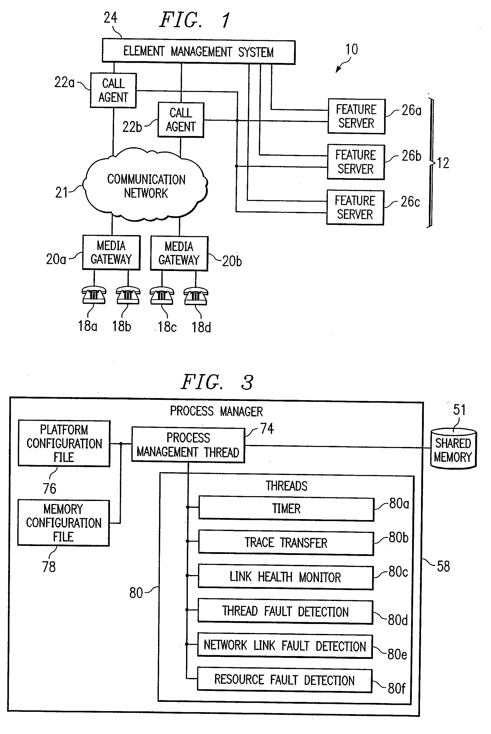
[0045]FIG. 1 is a block diagram illustrating one example of a system 10 for processing calls in a telecommunications network. System 10 may comprise, for example, a portion of a telecommunications network that includes, for example, a public switched telephone network (PSTN), an Internet Protocol (IP) network, and / or an asynchronous transfer mode (ATM) network. System 10 may provide Class 4 and Class 5 features to calls handling voice traffic over packet networks, which may allow a service provider to provide these features without a conventional Class 4 or Class 5 public switch.

[0046] Referring to FIG. 1, system 10 includes telecommunications devices 18 coupled to media gateways 20, which are coupled to call agent 22a and 22b through a communication network 21. Call agents 22a and 22b are coupled to an element management system 24 and any number of feature servers 26. Media gateways 20, call agents 22a and 22b, element management system 24, and feature servers 26 may communicate w...


PUM


Abstract

A method for tracking a process is disclosed. Requests are received from process threads according to a time order. A request requests a buffer entry operable to record a trace message from a process thread of a process. A first buffer entry is assigned to a first process thread associated with a trace message according to the time order. A second buffer entry is assigned to a second process thread according to the time order subsequent to the assignment of the first buffer entry. The trace message associated with the first process thread is written to the first buffer entry in response to the assignment of the first buffer entry.

Description

RELATED APPLICATIONS [0001] This application is a continuation of U.S. application Ser. No. 09 / 948,316 filed Sep. 6, 2001 and entitled “Recording Trace Messages of Processes of a Network Component”. [0002] This application claims benefit under 35 U.S.C. § 119(e) of U.S. Provisional Application Ser. No. 60 / 231,831, filed Sep. 6, 2000, entitled “OPTICALL.”[0003] This application is related to U.S. patent application Ser. No. 09 / 948,288, entitled “PROCESSING A SUBSCRIBER CALL IN A TELECOMMUNICATIONS NETWORK,”; to U.S. patent application Ser. No. 09 / 948,220, entitled “DATA COMMUNICATION AMONG PROCESSES OF A NETWORK COMPONENT,”; to U.S. patent application Ser. No. 09 / 948,314, entitled “PROVIDING FEATURES TO A SUBSCRIBER IN A TELECOMMUNICATIONS NETWORK,”; to U.S. patent application Ser. No. 09 / 947,743, entitled “MANAGING PROCESSES OF A NETWORK COMPONENT,”; to U.S. patent application Ser. No. 09 / 948,420, entitled “COMMUNICATING MESSAGES IN A MULTIPLE COMMUNICATION PROTOCOL NETWORK,”; to U....

Claims


Application Information

Patent Timeline
Patent Type & Authority Applications(United States)
IPC IPC(8): G06F9/44
CPCH04L12/2602H04L12/2697H04L43/50H04L43/0817H04L43/16H04L43/00
Inventor GOPAL, VENU P.SHENOY, GANESH N.
Owner CISCO TECH INC
Why Eureka
Try Eureka