Data communication device and the method thereof

a data communication and data technology, applied in data switching networks, instruments, frequency-division multiplexes, etc., can solve the problems of too much time for failure occurrence detection and compressed communication bandwidth within the network, and achieve the effect of shortening reducing the time taken for failure occurrence notification

Inactive Publication Date: 2007-07-26
ALAXALA NETWORKS
View PDF4 Cites 30 Cited by
  • Summary
  • Abstract
  • Description
  • Claims
  • Application Information

AI Technical Summary

Benefits of technology

[0058]Also, the same as with the second data communication system, the BFD is not operated between the first edge and the second edge, and when a failure occurs at the first access line, using the virtual circuit withdraw message, notification of the failure occurrence is made to be given from the first edge to the second edge, so it is possible to do notification of the failure occurrence in a short time without compression of the communication bandwidth within the fi...

Problems solved by technology

However, as noted above, between the customer edges (between CE1 and CE2), when failure occurrence was detected by operating the reachability verification protocol, there were the following kinds of problems.
Specifically, as the reachability verification protocol, for example when using the reachability monitoring function (called static polling) by periodically sending and receiving an echo request and echo reply message of ICMPv4/ICMPv6 between the customer edges (between CE1 and CE2), after a failure occurs at the other party access line, an actual timeout is det...

Method used


Image

  • Data communication device and the method thereof
  • Data communication device and the method thereof
  • Data communication device and the method thereof

Examples


first embodiment

A. First Embodiment

A-1: Constitution of the Embodiment

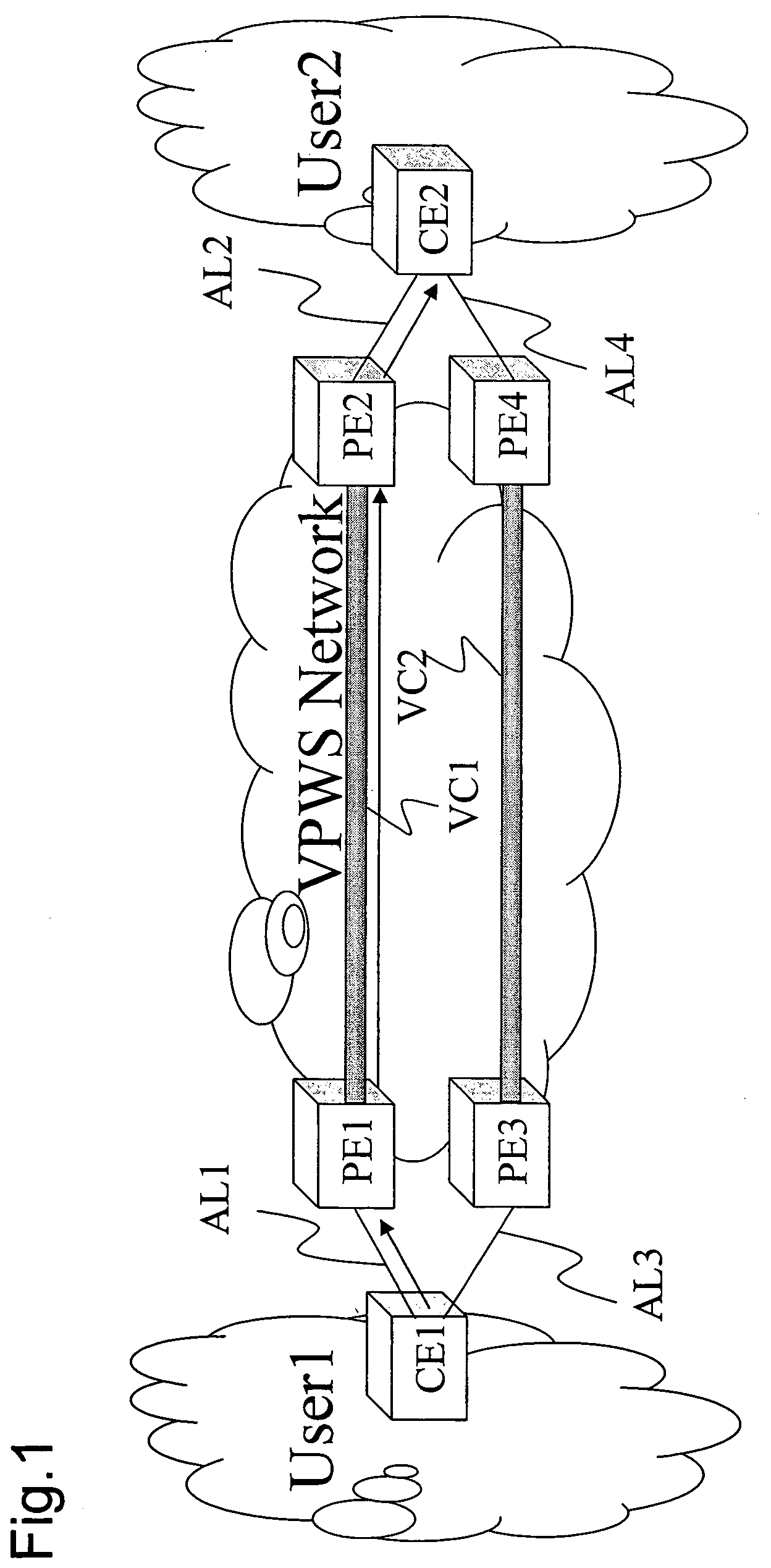
[0074]FIG. 1 is an explanatory drawing showing a network for which the data communication system is applied as the first embodiment of this invention.

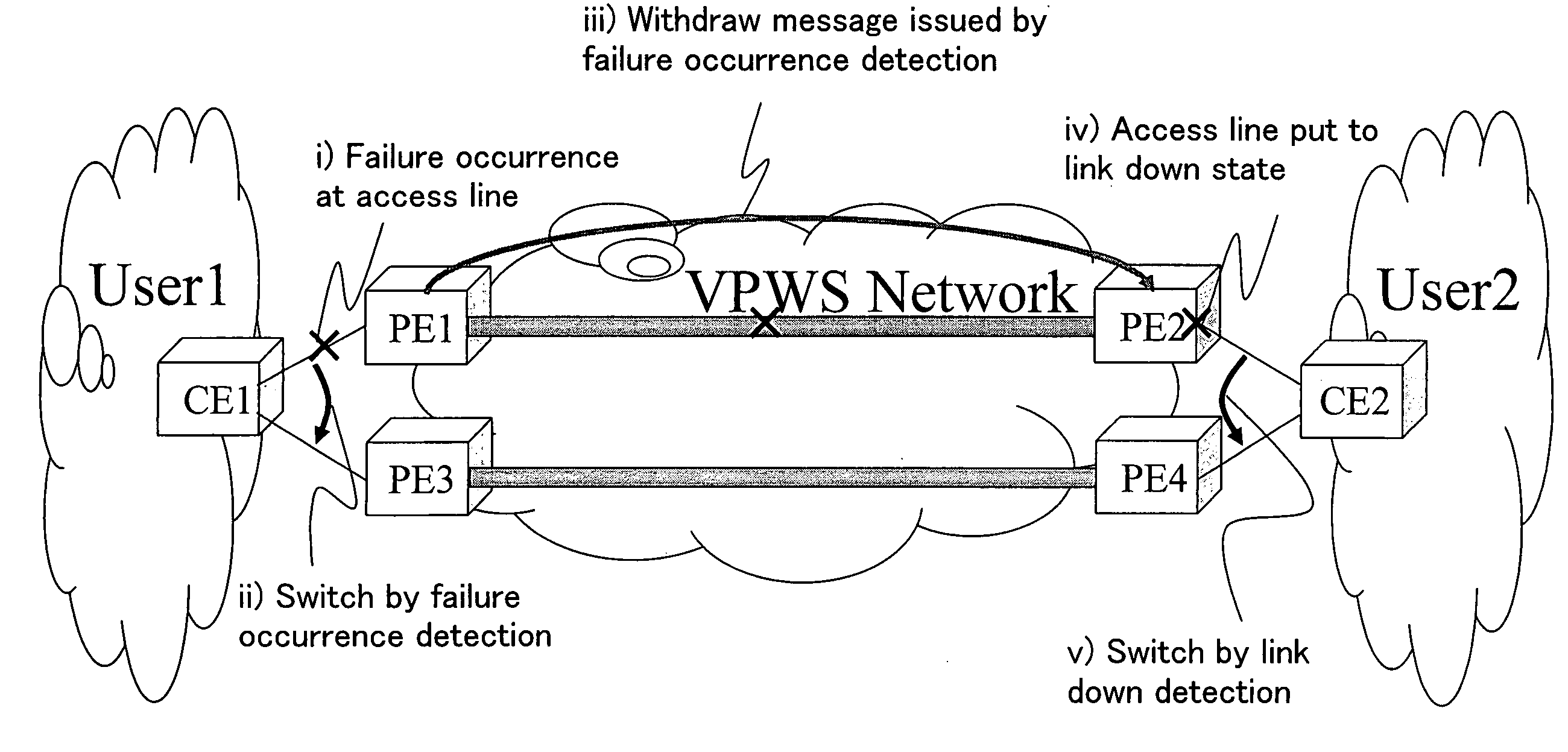
[0075]With this embodiment, as shown in FIG. 1, between User 1 which is one customer site and User 2 which is another customer site, there is a VPWS network which is an MPLS network of the service provider (SP), and for the one customer site User 1, between the customer edge CE1 which is at its edge part and the provider edge PE1 which is at one edge part at the VPWS network is connected by the access line AL1, and similarly, for the other customer site User 2, between the customer edge CE2 at the edge part and the provider edge PE2 at the other edge part at the VPWS network is also connected by the access line AL2. The access lines AL1 and AL2 that connect between CE and PE are connected point-to-point by an affiliated virtual circuit VC1 within the VPWS network. Then, the normal p...

second embodiment

B. Second Embodiment

[0091]Now then, for the first embodiment noted above, the provider edge and the customer edge, when a link down failure occurred at their own access line, detected that failure occurrence, and it was possible to perform the processes of step ii and step iii, but for failure other than link down, for example when a failure such as one line disconnect occurs, it is not possible to detect that failure occurrence.

[0092]In light of this, for the second embodiment of this invention, by using the BFD (Bidirectional Forwarding Detection) which is the reachability verification protocol, even when a failure such as one line disconnect occurs, it is possible to detect that failure occurrence. Note that here, one-line disconnect means a state of one of the lines being disconnected when the sending line and the receiving line are different lines.

B-1 : Constitution of the Embodiment

[0093]The basic constitution of this embodiment is the same as the constitution of FIG. 1, so th...


PUM


Abstract

When the provider edge PE1 detects the occurrence of a failure at the access line AL1, it sends the label withdraw message to the virtual circuit VC1, and when the provider edge PE2 receives the label withdraw message sent via the virtual circuit VC1, the access line AL2 is put to a link down state, and when the customer edge CE2 detects the link down state of the access line AL2, it switches from the normal path to the redundant path.

Description

INCORPORATION BY REFERENCE[0001]The present application claims priority from Japanese application JP2006-14686 filed on Jan. 24, 2006, the content of which is hereby incorporated by reference into this application.BACKGROUND OF THE INVENTION[0002]1. Field of the Invention[0003]The present invention relates to technology for notifying the occurrence of a failure when failure occurs on an access line connected with a network.[0004]2. Description of the Related Art[0005]In the past, using an MPLS (Multiprotocol Label Switching) network of a service provider (SP) between a certain customer site and another customer site, VPWS (Virtual Private Wire Service) is known as a service for performing point-to-point data communication via a layer 2 VPN (Virtual Private Network).[0006]FIG. 10 is an explanatory drawing showing an example of a network for which a typical VPWS is used. As shown in FIG. 10, with VPWS, there is an MPLS network between the User 1 which is one customer site and the User...

Claims


Application Information

Patent Timeline
IPC IPC(8): H04J3/14H04L45/24H04L45/247H04L45/50H04L69/40
CPCH04L45/02H04L45/04H04L43/0811H04L45/28H04L45/502H04L45/22
Inventor FUJITA, MANABUARAI, MASAYAWATANABE, KENINO, KENSUKE
Owner ALAXALA NETWORKS
Why Eureka
Try Eureka