Bottom weight device of a roller blind

a bottom weight and roller blind technology, applied in the direction of snap fasteners, door/window protective devices, buckles, etc., can solve the problems of not being perfect at all, achieve superior bottom weight effect, move more smoothly, and facilitate assembly

Inactive Publication Date: 2007-08-02
LINES UP INT
View PDF5 Cites 21 Cited by
  • Summary
  • Abstract
  • Description
  • Claims
  • Application Information

AI Technical Summary

Benefits of technology

[0005] The primary object of present invention is to provide an improved bottom weight device of a roller blind such that the bottom weight device can be assembled more conveniently and quickly and is provided with a superior effect of bottom weight, thereby enabling the roller blind to move more smoothly.
[0006] The aforementioned bottom weight device is composed of two rails and two side covers, wherein the two rails are roughly in a U-shape such that their bottom rims are formed with a proper arc. Symmetric longitudinal boreholes are located on the two rails and lock lumps corresponding to the boreholes of rails are located at inner rims of the two side covers, such that the two lock lumps are separated by a proper distance for inserting the lock lumps of two side covers into the boreholes of rails, respectively, in order to constitute a bottom weight device which enables a bottom end of the roller blind to reeve around the gap between the two rails, thereby allowing the roller blind to move up and down more smoothly and steadily, and preventing the roller blind from being lifted by a wind blow.

Problems solved by technology

However, the conventional bottom weight device is a cylindrical rod located at a bottom end of the roller blind, which is easier to be sliding, is not provided with a good effect of counter weight, and is more troublesome in assembling; therefore it is not perfect at all.

Method used


Image

  • Bottom weight device of a roller blind
  • Bottom weight device of a roller blind
  • Bottom weight device of a roller blind

Examples


Embodiment Construction

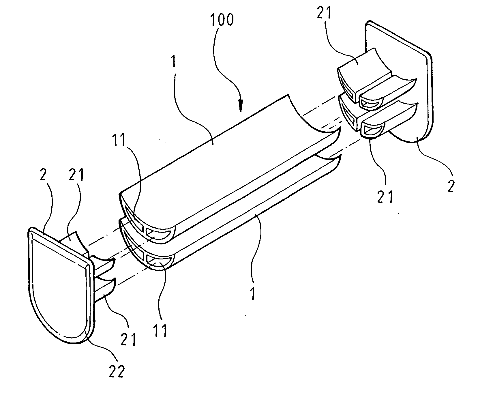
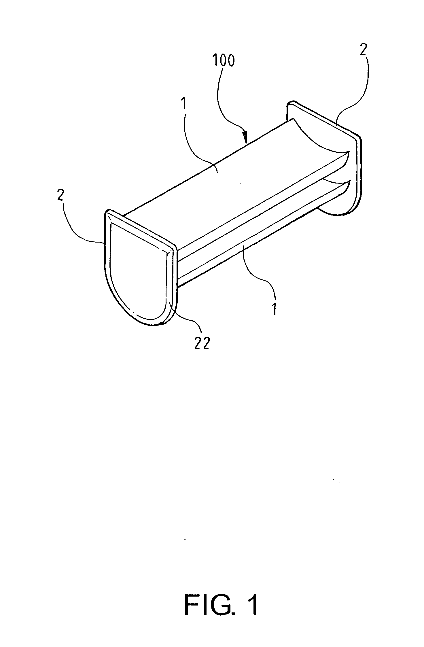
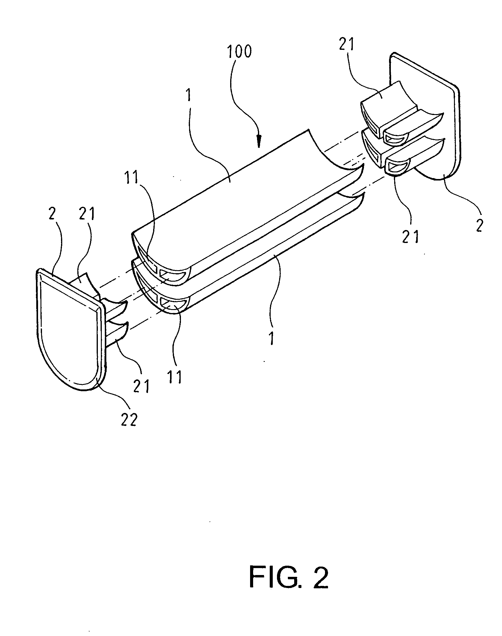
[0013] Referring to FIG. 1 and FIG. 2, the present invention comprises primarily two rails 1 and two side covers 2, wherein the two rails 1 are roughly in a U-shape, bottom rims of which are formed with an arc, and which are provided with symmetric longitudinal boreholes 11. Inner rims of the two side covers 2 are provided with lock lumps 21 corresponding to the boreholes 11 of rails 1, the lock lumps 21 are separated by a proper distance, and peripheries of the two side covers are inclined by about 10 degrees.

[0014] Through an assembly of the aforementioned structures, the two side covers 2 are fixed at two sides of rails 1 by latching the lock lumps 21 to the boreholes 11 of rails 1, respectively, so as to constitute a bottom weight device 100, which enables a bottom end of the roller blind to reeve around the gap between the two rails 1. Through a weight of the bottom weight device 100 and the arc of rail 1, the roller blind can move up and down more smoothly, and can be prevent...


PUM


Abstract

A bottom weight device of a roller blind is primarily composed of two rails and two side covers, wherein the two rails are roughly in a U-shape and are provided with longitudinal boreholes, and inner rims of the two side covers are provided with lock lumps corresponding to the boreholes of rails, with the two lock lumps being separated by a proper distance, thereby constituting a bottom weight device after inserting and fixing the lock lumps of two side covers into the boreholes of rails. Accordingly, a bottom end of the roller blind can reeve around the gap between two rails, and the roller blind can move up and down more smoothly and steadily, and can be prevented from being lifted by a wind blow.

Description

BACKGROUND OF THE INVENTION [0001] (a) Field of the Invention [0002] The present invention relates to a bottom weight device of a roller blind, and more particularly to a bottom weight device which can be conveniently and quickly assembled, and can enable the roller blind to move up and down smoothly and steadily. [0003] (b) Description of the Prior Art [0004] It is well known that a bottom end of an ordinary roller blind usually reeves around a bottom weight device to enable the roller blind to move steadily due to that its center of gravity is located at a lower end, such that the roller blind can move up and down more smoothly, and can be prevented from being lifted by a wind blow. However, the conventional bottom weight device is a cylindrical rod located at a bottom end of the roller blind, which is easier to be sliding, is not provided with a good effect of counter weight, and is more troublesome in assembling; therefore it is not perfect at all. SUMMARY OF THE INVENTION [0005...

Claims


Application Information

Patent Timeline
Patent Type & Authority Applications(United States)
IPC IPC(8): A44B11/00
CPCE06B9/17046Y10T24/40E06B9/42E06B9/388
Inventor CHIEN, GOW-TEN
Owner LINES UP INT
Why Eureka
Try Eureka