Heat transporting unit and electronic device

a technology of heat transporting unit and electronic device, which is applied in the direction of indirect heat exchangers, lighting and heating apparatuses, laminated elements, etc., can solve the problems of inability to ensure the optimal operation of the device, the size of such a compact electronic part is small, and the performance degradation of the device or the industrial apparatus can not be guaranteed, so as to achieve the effect of improving the heat transporting efficiency and high efficiency

Inactive Publication Date: 2012-08-23
MOLEX INC
View PDF6 Cites 0 Cited by
  • Summary
  • Abstract
  • Description
  • Claims
  • Application Information

AI Technical Summary

Benefits of technology

[0012]An object of the Present Application is to provide a heat transporting unit, operable to flexibly deal with various kinds of heating elements targeted for cooling, and to transport heat taken from a heating element at high speed. A heat transporting unit according to the Present Application can rapidly and effectively transport heat from a heating element in a constant first direction. To be more specific, even when the heating element is small compared to the heat transporting unit, heat transportation corresponding to a quantity of heat generated by the heating element is performed since the heat is transported via every path of the paths that are composed by dividing an internal space therein. When heat transportation is insufficient only using a refrigerant sealed into a certain path, the refrigerant may be exchanged via a communication path. Therefore, the efficiency of heat transportation in the paths is flexibly improved.
[0013]Additionally, the evaporated refrigerant diffuses in the paths, and the condensed refrigerant circulates in grooves. As such, the evaporated refrigerant and the condensed refrigerant neither meet nor interfere with each other. As a result, moving velocities of the refrigerants become higher, and the heat transporting unit can transport heat with high efficiency. At this time, capillary channels provided with an end part of the heat transporting unit enable the condensed refrigerant to come and go between the paths and the grooves. When surface treatment, such as chamfering, metal plating or the like, is performed on at least a part of the paths and the grooves, the refrigerants can move more smoothly.

Problems solved by technology

However, these electronic devices include heating elements that generate heat as a result of the current running therein.
When the temperature in the heating element becomes higher than a constant temperature, a problem exists in that optimal operation of the device can not be guaranteed.
As a result, the heat may influence other parts, and may cause performance degradation of the device or the industrial apparatus.
Of course, the size of such a compact electronic part is small.
Difficulties may arise in that the refrigerant evaporated by the heat receiving member, and the refrigerant condensed by the heat radiating member, may not easily enter the pipe.
Thus, the speed of heat transportation in the heat transporting member may be slow.
However, when cooling a plurality of compact heating elements, such as LEDs, since the heat generation area of the heating element and the heat generation and transporting areas of the heat pipe are unbalanced, the efficiency of heat transportation, relative to the size and ability of the heat pipe, is poor.
Further, since the amount of the refrigerant is large relative to the caloric value of the heating element, the efficiency of refrigerant evaporation is also poor.
Thus, the efficiency of the circulation becomes poor as well.
However, the pores are divided into pores wherein the heat transporting is intense and pores wherein the heat transporting is poor, according to the number and the caloric value of the heating element connecting to the heat pipe.
Thus, it is possible to diffuse the evaporated refrigerant, but impossible to efficiently circulate the condensed refrigerant.
In addition, although it is preferred to transfer the heat of the heating element to a position away from the heating element at high speed, heat can not be transported with a high degree of efficiency in the electronic board and the heat pipe of the ‘585 Application.
Thus, there is a limit for the efficiency of heat transportation.
Further, as mentioned above, in a cooling device using a conventional heat pipe, although it deals with various heating elements, the heat can not be transported at high speed.

Method used


Image

  • Heat transporting unit and electronic device
  • Heat transporting unit and electronic device
  • Heat transporting unit and electronic device

Examples


Embodiment Construction

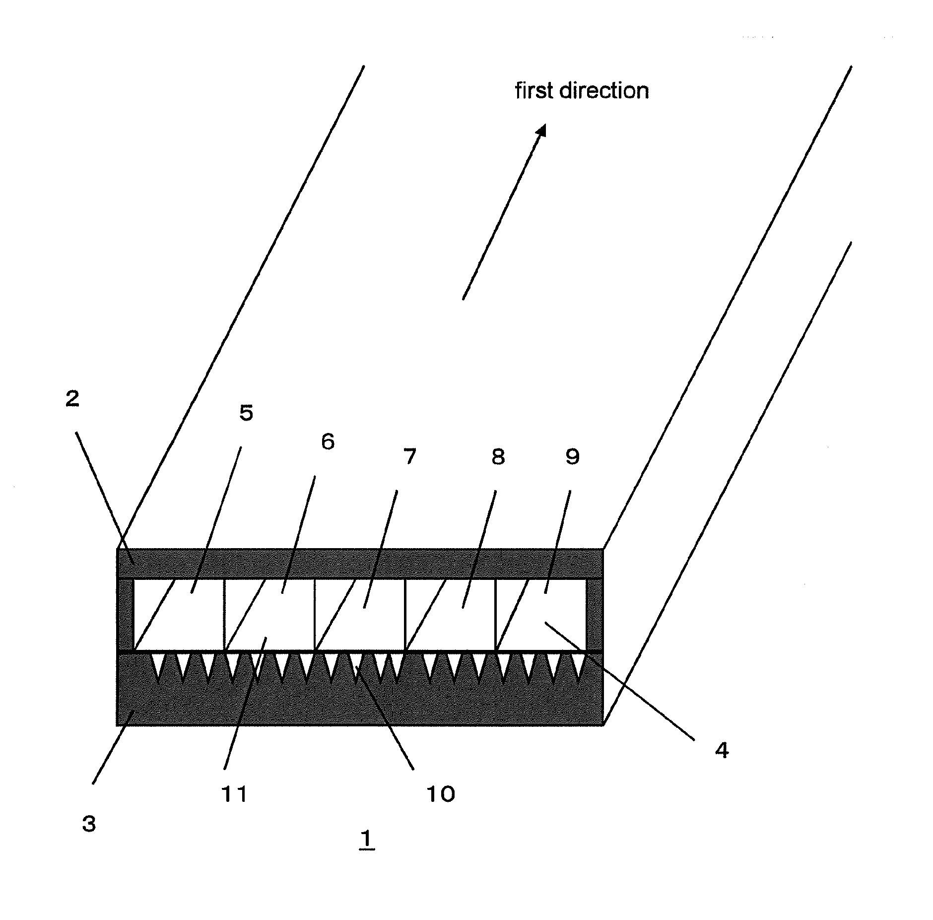
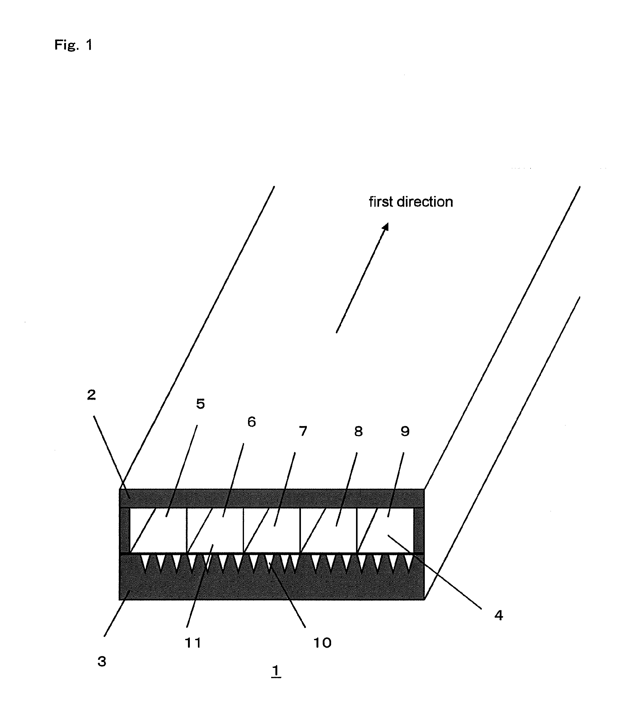
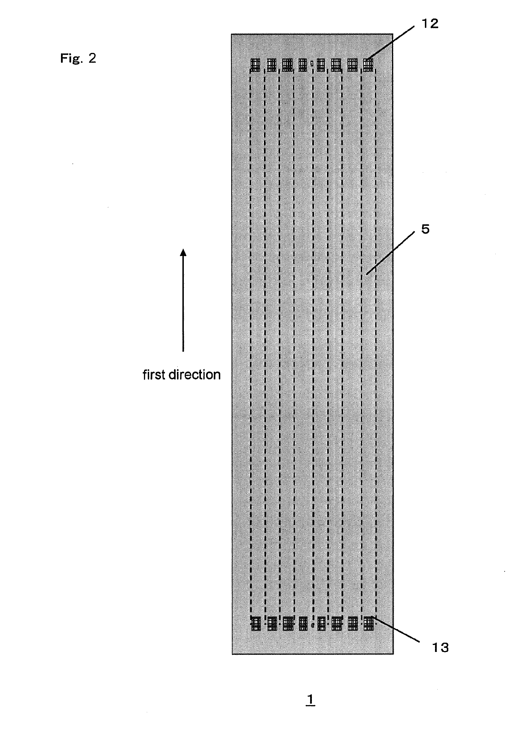
[0037]While the Present Application may be susceptible to embodiment in different forms, there is shown in the Figures, and will be described herein in detail, specific embodiments, with the understanding that the disclosure is to be considered an exemplification of the principles of the Present Application, and is not intended to limit the Present Application to that as illustrated.

[0038]In the illustrated embodiments, directional representations—i.e., up, down, left, right, front, rear and the like, used for explaining the structure and movement of the various elements of the Present Application, are relative. These representations are appropriate when the elements are in the position shown in the Figures. If the description of the position of the elements changes, however, it is assumed that these representations are to be changed accordingly.

[0039]In addition, a “heat pipe” shall mean a member, a part, an apparatus or a device for refrigerating or cooling a heating element. Pref...


PUM


Abstract

A heat transporting unit comprises an upper plate, a lower plate opposing the upper plate, an internal space formed by the upper plate and the lower plate and operable to enter a refrigerant, a plurality of paths dividing the internal space in a first direction, and a plurality of grooves being provided at a bottom surface of the internal space. The plurality of the paths and the plurality of the grooves are connected by capillary channels in a region, and are divided by sidewalls in another region.

Description

REFERENCE To RELATED APPLICATIONS[0001]The Present Application claims priority to prior-filed Japanese Patent Application No. 2009-186534, entitled “Heat Transporting Unit And Electronic Device,” and filed 11 Aug. 2009, the contents of which is fully incorporated in its entirety herein.BACKGROUND OF THE PRESENT APPLICATION[0002]The Present Application relates, generally, to a heat transporting unit and an electronic device operable to transport heat received from a heating element, e.g., a semiconductor integrated circuit (IC), a Light Emitting Device (LED), a power device or an electronic device.[0003]Electronic devices, such as a semiconductor ICs, LEDs or other power devices, typically have many uses, such as in industrial apparati or the like. However, these electronic devices include heating elements that generate heat as a result of the current running therein. When the temperature in the heating element becomes higher than a constant temperature, a problem exists in that opti...

Claims


Application Information

Patent Timeline
Patent Type & Authority Applications(United States)
IPC IPC(8): F28F3/12
CPCF28D15/046F28D15/0233
Inventor OHSAWA, KENJITSURUTA, KATSUYA
Owner MOLEX INC
Why Eureka
Try Eureka