
Load hook

a technology of load hooks and hooks, applied in the field of load hooks, can solve the problems of neither easy catchment or sticking of the load hook, and achieve the effect of less risk of injury

Inactive Publication Date: 2007-08-02
DEMAG AG
View PDF9 Cites 6 Cited by
  • Summary
  • Abstract
  • Description
  • Claims
  • Application Information

AI Technical Summary

Benefits of technology

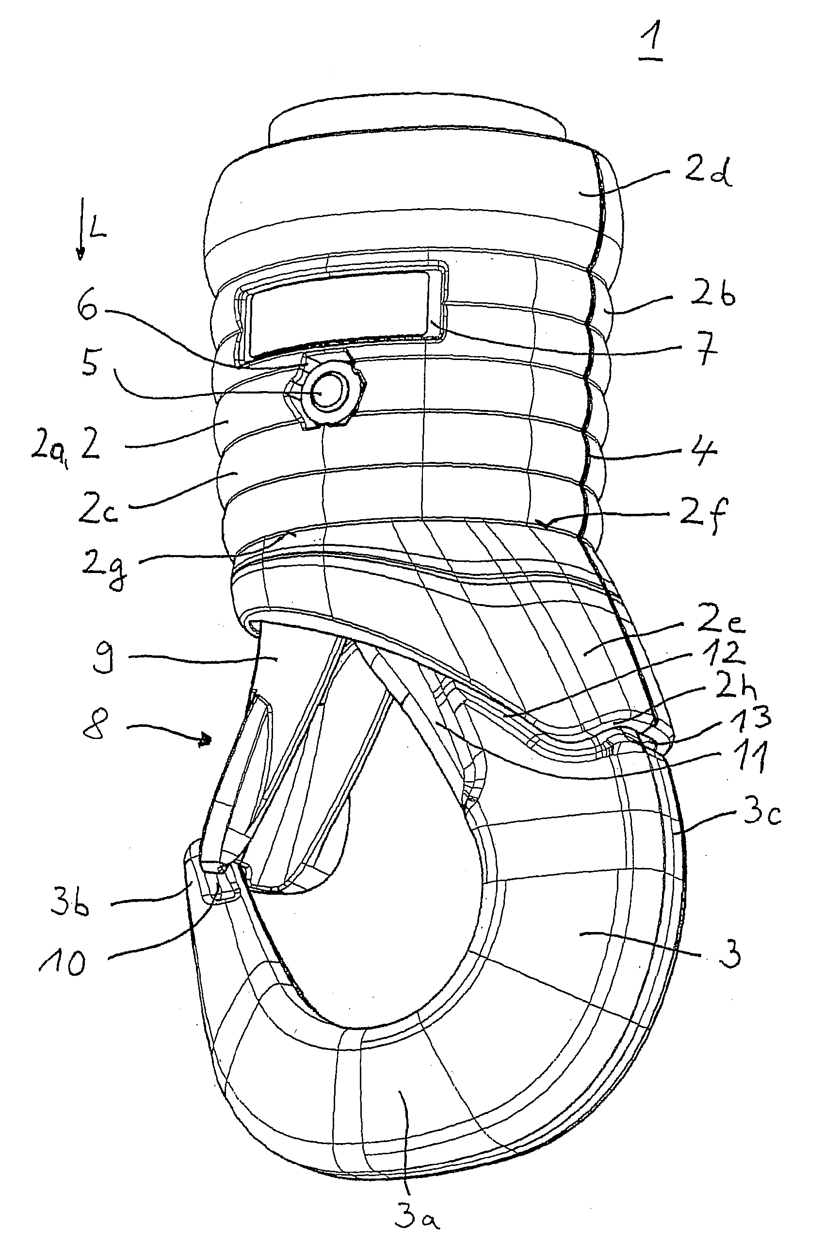
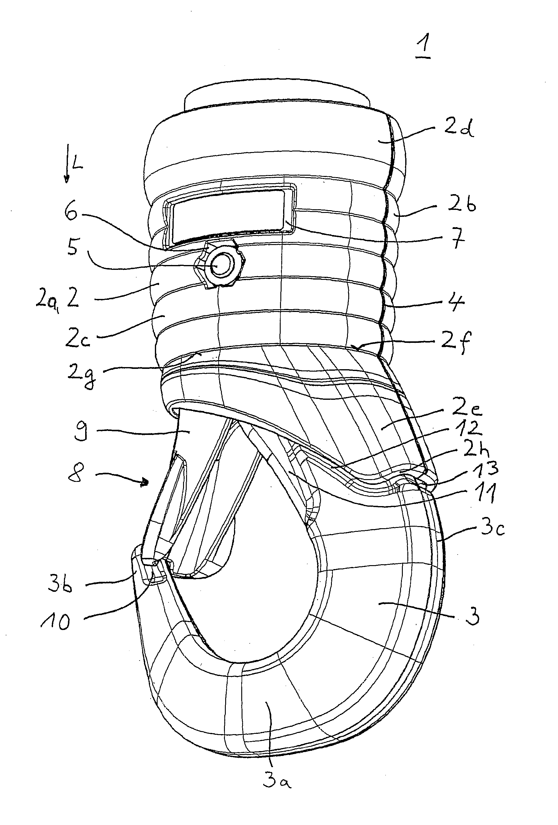
[0005] According to the invention, a load hook includes a hook fastened to a hook tackle. A secure construction that is safe to handle is achieved in that a cover region is at least partially arranged between the hook tackle and the hook, such that the hook is partly covered starting at the outer contour of the hook tackle. This configuration will create a larger grasping surface for the manual holding or pulling forces applied by a user, such as when using the hands. The larger bearing surface prevents the user's hand from slipping off with a concomitant uncontrolled swaying of the load hook. Thus, there is less risk of injury. Furthermore, the hand cannot slip off and get injured by the step-like transition zone, since this is covered. Neither can the load hook get easily caught or stuck.
[0008] Since the user's ball of the thumb usually grasps the back side of the hook, it is provided that the length of the cover region increases from the hook mouth securement to the back side of the hook, in the lengthwise direction of the hook. This configuration further increases the bearing surface for the hand.
[0009] Optionally, the hook may be stationary relative to the hook tackle. Thus, the lengthened cover region can be easily adapted to the position of the hook.
[0011] To achieve a gentle transition between hook and hook tackle, avoiding abrupt contours, the cover region may taper, starting at the outer contour of the lower end of the hook tackle in the region of the hook, toward the outer contour of the hook, and its back side opposite the opening of the hook.

Problems solved by technology

Neither can the load hook get easily caught or stuck.

Method used


Image

  • Load hook
  • Load hook

Examples


Embodiment Construction

[0015] The load hook 1 comprises a hook tackle 2 and a hook 3. The hook tackle 2 here has the usual function of a connection element, in order to suspend the hook 3 from a chain or cable (not shown). A design for a chain shall be assumed. The hook tackle 2 also has a housing function, making it possible to accommodate and enclose the ends of the hook 3 and of the chain, facing each other.

[0016] In the present embodiment of the load hook 1, the hook tackle 2 is divided in the lengthwise direction L of the load hook 1, i.e., in the vertical direction for a load hook 1 hanging freely from a chain, into a first half 2a and a second half 2b. The partition occurs in the middle, so that the halves 2a and 2b are basically the same size. Furthermore, the halves 2a and 2b each have generally flat parting planes 4, and when assembled together they complement each other to form a barrel-shaped or cylindrical body. In addition, the hook tackle 2 is provided with a contoured grasping region 2c o...


PUM


Abstract

The invention concerns a load hook with a hook fastened to a hook tackle that can be safely handled. A cover region is arranged at least partially between the hook tackle and the hook, such that the hook is covered starting at the outer contour of the hook tackle.

Description

[0001] The invention concerns a load hook with a hook fastened to a hook tackle. BACKGROUND OF THE INVENTION [0002] A load hook is known from German utility model DE 298 17 206 U1, being attached by a chain to a hoisting machine. The load hook is composed in familiar manner of a hook to take up the load and a hook-supporting housing known as the hook tackle, by which the hook is connected to the chain. The hook tackle is divided into two halves in the lengthwise direction of the load hook and has a barrel-shaped appearance. The two halves of the hook tackle are joined together by two screws running transversely to the lengthwise direction of the hook. In the screwed-together condition, the flat parting planes of the halves of the hook tackle lie against each other. In the region of the flat parting planes, in the lengthwise direction of the load hook, an upper and a lower recess are provided, each of which emerges through adjacent upper and lower opening regions into the top and the...

Claims


Application Information

Patent Timeline
Patent Type & Authority Applications(United States)
IPC IPC(8): B66C1/34
CPCB66C1/34
Inventor EISING, RALFGERSEMSKY, UDOLICHTENVORT, UWEWALLOSCHEK, THILO
Owner DEMAG AG
Learn More