Bit driver and method for its use

a driver and bit technology, applied in the direction of manufacturing tools, slitting machines, hand hammers, etc., can solve the problems of reducing the efficiency of equipment that relies on them, cutting bits exposed to extreme frictional and impact forces, and wear and damage to cutting bits, so as to achieve less risk, less risk, and more striking or hammering force

Pending Publication Date: 2019-03-14
VERKLEY STEVEN GERARD
View PDF19 Cites 3 Cited by
  • Summary
  • Abstract
  • Description
  • Claims
  • Application Information

AI Technical Summary

Benefits of technology

[0010]The present invention provides a device and a method for inserting a cutting bit into a receptacle bore of a cutting bit holder or directly into a cutting equipment. The device and method avoid striking directly the cutting tip of the cutting bit. The device and method provide for more striking or hammering force with less risk of injury and less risk of glancing-blows that can injury or damage the cutting bit holder or cutting equipment, and better stability and control of the positioning and alignment of the cutting bit as it is being hammered into the receptacle bore.

Problems solved by technology

During the operation of such roadway surface reclaiming machines, the cutting bits are exposed to extreme frictional and impact forces.
Although these bits, described above, are typically manufactured from hardened materials, wear and damage to the cutting bits is inevitable.
As the cutting bits wear, the efficiency of the equipment that relies upon them is reduced, slowing the reclamation process and increasing the burdens imposed upon the cutting bit holders, the cutting drums and the equipment that drives these devices.
This leads to delay and increased costs for additional maintenance and labor.
However, typical road surface reclamation devices use a large number of cutting bits, thus, the replacement of the cutting bits is a time consuming process, largely because the manual removal and reinstallation cutting bits is often tedious and slow.
Thus, replacement of the bits is expensive, both requiring the extended attention of one or more trained mechanics, and because all road reclamation operations must cease during replacement of the cutting bits.
When circumstances dictate that cutting bits must be replaced during regularly scheduled reclamation activities, hundreds of labor hours can be lost.
This method of inserting a cutting bit can cause injury, since the bit is usually held in position for striking by a hand or fingers.
Also, striking the head of the hammer onto the hardened cutting bit, and particularly onto the carbide tip, can dimple and damage the head of the hammer so badly that shards of steel can be thrown off the hammer head and into the air, possibly causing injury.
And, striking the head of the hammer onto the carbide cutting tip may cause micro fracture damage to the cutting tip of the bit.

Method used


Image

  • Bit driver and method for its use
  • Bit driver and method for its use
  • Bit driver and method for its use

Examples


Embodiment Construction

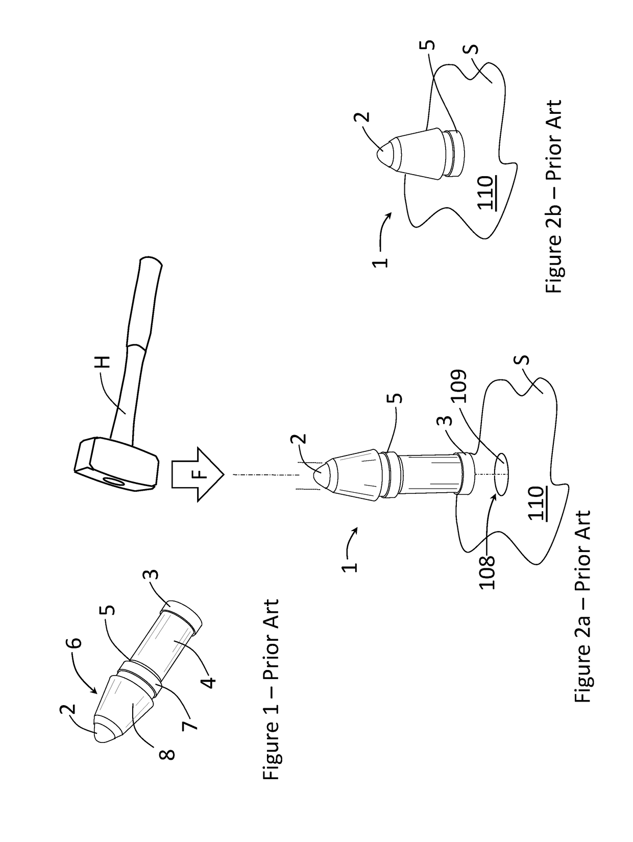
[0022]FIG. 1 shows a cutting bit 1 of the prior art, having an elongated cylindrical body 4 with a base end 3 and a bit end 6 having a cutting tip 2. A shoulder 5 separates the body 4 and the bit end 6, having a peripheral diameter 7.

[0023]FIG. 2a shows a conventional means for inserting a cutting bit 1 into a receptacle bore 109 in a cutting bit holder (or cutting equipment) 110. The base end 3 of the cutting bit 1 is held, usually by hand, over the opening 108 of the receptacle bore 109, and a user drives by force the cutting bit 1 into the receptacle bore 109 using a hammer, by striking the head of the hammer onto the cutting tip 2, until the shoulder 5 seats onto the tool surface around the opening 108, as shown in FIG. 2b.

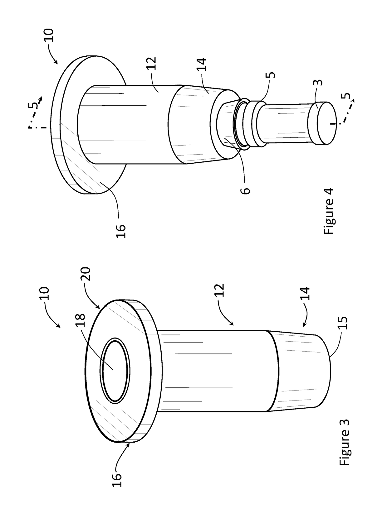
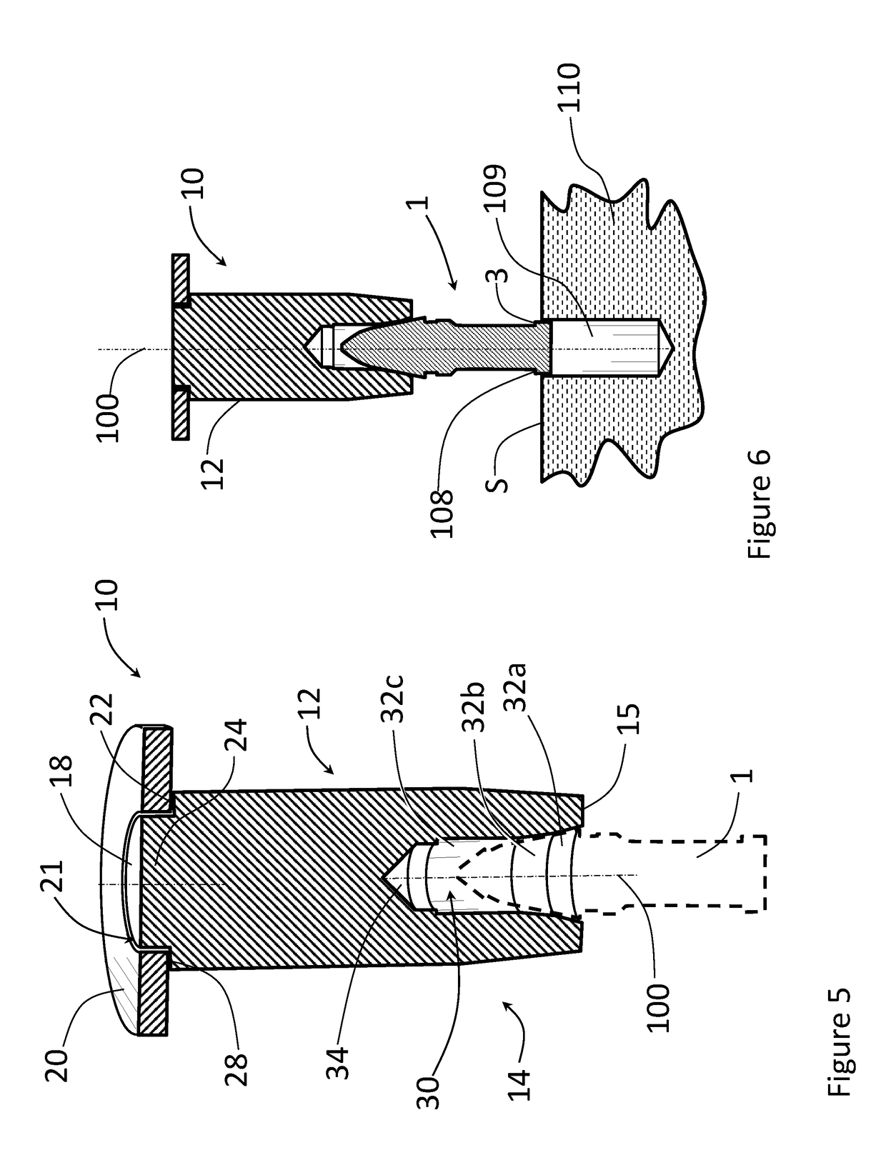
[0024]FIG. 3 shows a bit driver 10 having an elongated body 12 extending to a base end 14 that has a shaped cavity 30 in the distal face 15, the cavity 30 configured and shaped to hold and stabilize the bit end 6 of a cutting bit 1. The cavity extends along a...


PUM


Abstract

A bit driver for a cutting bit having an elongated body configured for being grasped by a user, and a lower end having a distal face. A shaped cavity is formed into the distal face, extending into the elongated body, and has one or more sections, each having a tapered annular surface that is configured to conform to an outer surface of a bit end of a conventional cutting bit. The tapered annular surface holds the cutting bit aligned along an axis of the elongated body. The bit driver also includes a driving end opposite the lower end having a target surface that has a diameter or average effective dimension larger than the diameter of the elongated body. The driving end receives an impact delivered by a hammer to insert the base end of the cutting bit into a receptacle bore of a cutting bit holder or cutting equipment.

Description

CROSS-REFERENCE TO RELATED APPLICATION[0001]This application claims the benefit of U.S. Provisional Patent Application No. 62 / 556,652, filed on Sep. 11, 2017, the disclosure of which is incorporated herein by reference.FIELD OF THE INVENTION[0002]The present invention generally relates to a tool for inserting cutting bits used in a cutting equipment, such as a roadway reclaiming equipment or an auger.BACKGROUND OF THE INVENTION[0003]Cutting bits are used in the heavy construction industry to cut and bore through rock and earth in the construction of highways, bridges, tunnels, dams and buildings of all types. Typical roadway surface reclaiming machines disclosed in the prior art include rotary driven cylindrical drums with holders holding fixed one or more cutting bits which scarify and mine the top portion of an asphaltic road surface. Conventional cutting bits can have. An alloy steel body that is heat-treatment hardened for high toughness and durability, and a tungsten carbide ti...

Claims


Application Information

Patent Timeline
Patent Type & Authority Applications(United States)
IPC IPC(8): B25B27/02B25D1/00
CPCB25B27/02B25D1/00E21C35/18B25B27/04
Inventor VERKLEY, STEVEN GERARD
Owner VERKLEY STEVEN GERARD
Why Eureka
Try Eureka