Multi-surface object end manual filing tool

a multi-surface object and filing tool technology, applied in the direction of filing/rasping tools, grinding machines, filing/rasping devices, etc., can solve the problems of rough inner and outer edges of cut strut ends, needing to be filed/abraded, dangerous sharpness, etc., to achieve the effect of safe and quick manner

Active Publication Date: 2015-10-08
URSULIAK TARAS
View PDF11 Cites 4 Cited by
  • Summary
  • Abstract
  • Description
  • Claims
  • Application Information

AI Technical Summary

Benefits of technology

[0007]Since filing work pieces having multiple nonlinear rough or sharp surfaces may require substantial repositioning of either the work piece or the device, it would be desirable if a metal file or abrading device existed that could file the sharp or rough surfaces of certain work pieces without having to substantially adjust the position of t

Problems solved by technology

For example, since metal strut has a hollow interior, when cut, both the inner and outer edge

Method used


Image

  • Multi-surface object end manual filing tool
  • Multi-surface object end manual filing tool
  • Multi-surface object end manual filing tool

Examples


embodiment 8

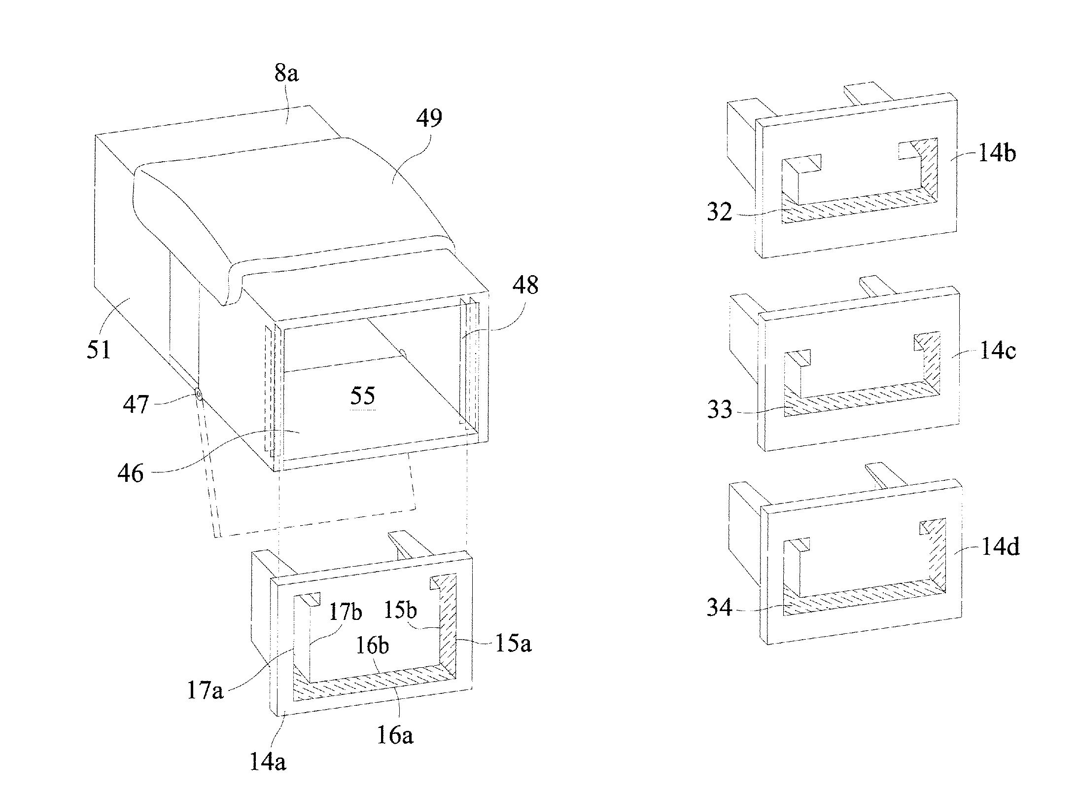
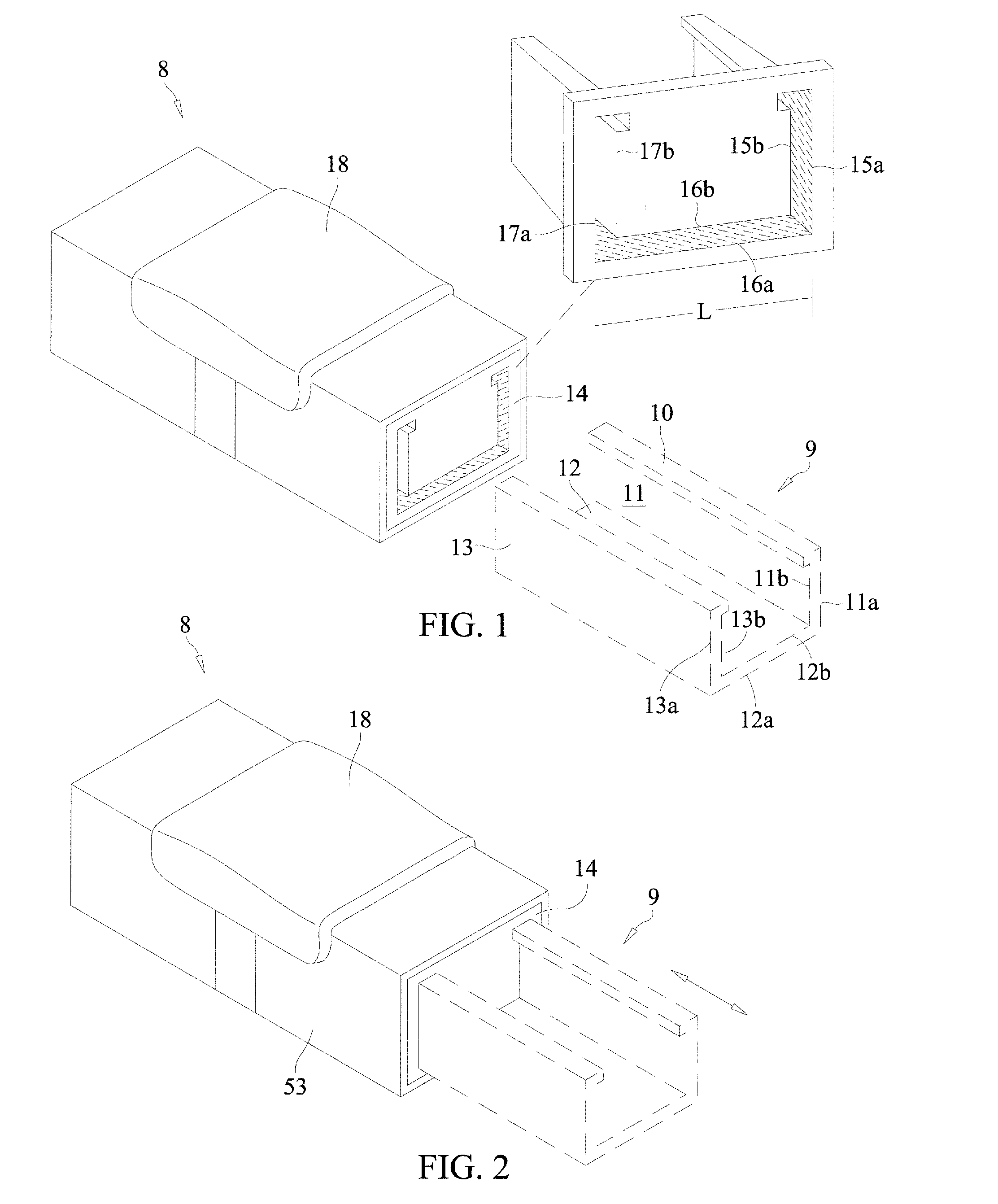
[0033]Embodiments and shapes of the device may vary according to desired function and preference. In particular, the precise styles, designs, dimensions, and configurations of filing surfaces, and device ends comprising such filing surfaces, may vary according to the surfaces (and / or edges thereof) of an object to be filed. For example, as shown in FIG. 5, although one device end 14a may comprise filing surfaces 15a, 16a, 17a, 15b, 16b, 17b having certain sizes and dimensions, other device ends 14b, 14c, 14d (of a similar style of the device embodiment 8 shown in FIGS. 1-2) may comprise filing sets of surfaces 32, 33, 34 of different sizes and cross-sectional lengths.

[0034]In addition, the amount or distance filing surfaces 14a, 15a, 16a, 14b, 15b, 16b of a device end 14a (for the similar style of the device embodiment 8 shown in FIGS. 1-2) may extend into the device 8a from the device end 14a, and the degree and direction (if any) to which the filing surfaces 14a, 15a, 16a, 14b, 15...

embodiment 14

[0035]Moreover, the device ends 14a, 14b, 14c, 14d of the device embodiment 14 shown in FIG. 5, and the device ends 36a, 36b, 36c, 36d, 36e of the device embodiment shown in FIG. 6, may be removable, interchangeable, and replaceable (for example, for when a particular filing surface has worn dull through usage). The manner in which the removable, interchangeable, and replaceable device ends may be inserted or attached to the device may also vary according to embodiment. For example, in the embodiment of the device 35 shown in FIG. 6, device ends 36a, 36b, 36c, 36d, 36e may fit directly onto the device, and in the embodiment of the device 8a shown in FIG. 5, a bottom side 46 of the device 8a may be hinged 47 and fall away, allowing the device ends 36a, 36b, 36c, 36d, 36e to slide securely up and into the device 8a in tracks of grooves 48.

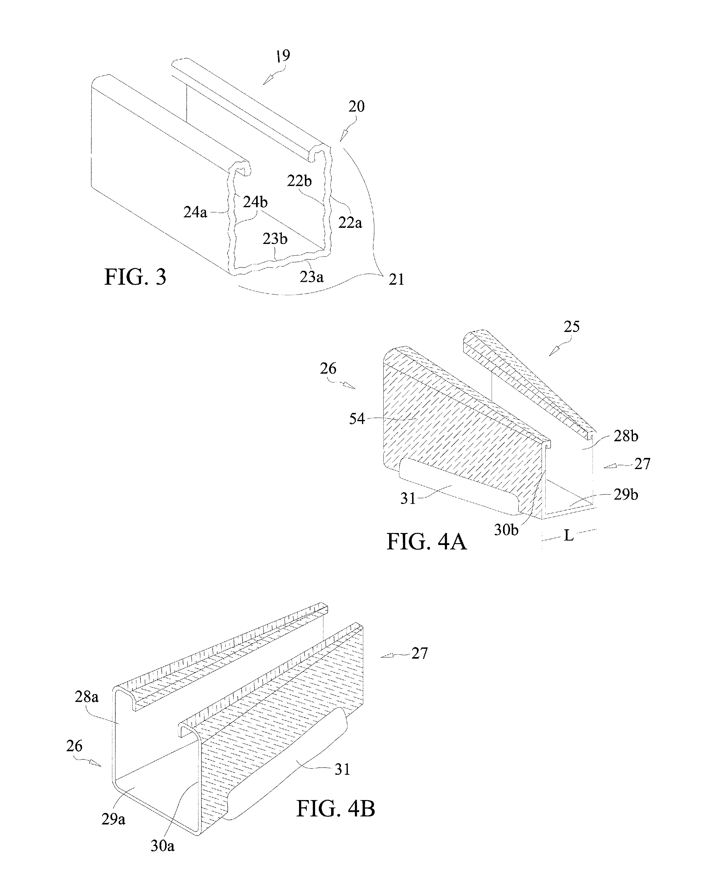
[0036]As shown in FIGS. 4A, 4B, 5, and 6, the hand controlled parts (i.e., handle / grip) 18, 31, 49, 50 and the bodies 41, 51, 52, 53, 54 of differen...


PUM

PropertyMeasurementUnit
Angleaaaaaaaaaa
Pressureaaaaaaaaaa
Angleaaaaaaaaaa

Abstract

A device for filing and/or abrading the multiple surfaces and/or edges of an object end so that they are less sharp, rough, dangerous, or so that they better conform to a desired shape. Embodiments of the device may comprise filing surfaces for filing the multiple object surfaces and/or edges thereof without requiring substantial repositioning of either the device or the object with surfaces and/or edges being filed. Moreover, embodiments of the device may be useful for filing sets of both the inner and outer object surfaces and/or edges thereof without requiring substantial repositioning of either the device or the object, and therefore in a more efficient and less dangerous manner. It is anticipated that some embodiments may comprise filing surfaces arranged in a manner configured to file the surfaces and/or edges of a strut end.

Description

FIELD OF INVENTION[0001]The present invention is in the technical field of filing and abrading devices. More particularly, the embodiments of the invention described and shown herein relate to the filing of potentially dangerous object ends having multiple surfaces and edges arranged at substantially nonlinear angles.BACKGROUND[0002]Various inventions have been created to file or abrade the surfaces and / or edges of objects, particularly when said object surfaces and / or ends are rough or dangerously sharp. Metal files, for example, come in a variety of shapes, materials, and teeth, but most are limited to a similar basic design: an elongated flattened blade having one or more filing surfaces, with forward-facing cutting small teeth on said surface(s). When pressure is applied from the teeth of the metal file to a rough or sharp surface of a work piece and the metal file is pushed over the work piece, the cutting action of the sharp teeth can smooth the surface. Different configuratio...

Claims


Application Information

Patent Timeline
IPC IPC(8): B23D71/08
CPCB23D71/08Y10T29/44B23D71/04B24B9/00B24B9/007B24D15/00B24D15/04B24D15/045Y10T29/442Y10T29/444Y10T29/446Y10T29/448Y10T29/45B23D71/10
Inventor URSULIAK, TARAS
Owner URSULIAK TARAS
Why Eureka
Try Eureka